Thursday, April 3, 2014

MELD v1 boards and Olight S10


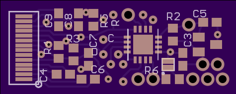
For quite some time now I’ve had my RGBWUV multicolor lights and my ultimate flashlight code white lights working well, but always had to have the two separate lights in order to get all the features. I decided it was finally time to combine them into the do-everything light, and so I designed the MELD board:


MELD is for Multicolor Edc Light Driver. Here were my requirements for the design:
  • 4 output channels with PWM dimming for RGBW
  • 1 output channel with on/off control for UV
  • Operate from a single lithium cell of primary or secondary type (input voltage 2.0-4.2V)
  • Consistent output at any battery level
  • Controlled with momentary switch
  • 5/8” diameter or less to fit in small lights
  • 1A output on white channel, ~350mA on colors
  • Colors able to be mixed (channels with varying Vf can be operated simultaneously)
  • Firmware can be upgraded while board is installed in a light
Operating from primary or secondary cells meant the output voltage could be higher or lower than the input voltage depending on LED color and charge level, so I needed buck and boost functionality in the switching converter. The other deciding factor about the converter was the mixing capability. A constant-current source is ideal for LEDs and provides true regulation (immune to temperature-based Vf changes), but if LEDs of dissimilar Vf are both connected to a CC source, only the lower Vf LED will light.

The best solution would be to have individual regulators for each channel, but the size requirements didn’t allow for that. My solution was to find a part that would regulate to a constant voltage, and then run the LEDs from that source with individual current-limiting resistors. This creates waste in the resistors, but if the bulk voltage is closely matched to Vf the waste can be minimized. I found a part that fit, the LM3668. This part will switch automatically between buck and boost modes to maintain a 3.3V output. It is also extremely small and runs at 1.6MHz which means a small inductor can be used.

To run the board I went with PIC16F1824. This part has 4 PWM peripherals to run the output channels and enough I/O for the rest of the functions. In addition to the 5 outputs, it has the switch input and an enable output to the regulator that shuts it down when in standby. From an early prototype of this, I learned one other trick that you can see in the schematic: the microcontroller gets its supply voltage through a dual Schottky diode, which supplies it either from battery voltage or from the converter output, whichever is higher. Without this, with the µC running straight from battery, if the battery is drained (2-2.5V) the microcontroller’s outputs to the FET gates aren’t above the gate threshold and it can’t turn the LEDs on. With the diode, the µC runs from battery while in standby, but when in operation the converter is switched on and it supplies 3.3V to operate the microcontroller (unless the battery is a rechargeable at a high charge level, in which case this doesn’t matter).


The PCB design was challenging because it is so small, but I managed to fit everything. The converter and microcontroller are on top, and the 5 FETs and resistors are on the bottom, along with the positive battery contact:

While I waited for the PCBs to come in, I started coding. This project was essentially a rewrite of my Skyray King software (which was based on D10 software), but writing it in C this time. Writing in C forced me to give it a much cleaner structure and it leaves the firmware open to easier upgrades in the future. I was very happy with the way the code came out. The main control logic is a big state machine that runs all the time, taking inputs from the switch debouncer that runs in the background. Everything else is triggered from a 1ms interrupt that runs timers and fires the switch debounce routine. I’m still looking for an alternate site to upload code to since Google Code stopped taking uploads, so if you want a copy leave a comment. Here’s a list of the features included in the latest version:
  • All modes:
    • Turn on and off by short click
    • Mode memory in all cases (restore last mode after turning off and on)
    • Ramping by holding switch while on
    • Ramping reverses direction when initiated if it has been less than 3 seconds since the last ramp
    • Smart momentary from off (short click latches on, long press is momentary)
    • Shortcut to primary level from on by double click
    • Shortcut to max by click-press
      • If level is currently max, shortcut to min instead
      • If primary level is set to max, shortcut to min instead
      • If held down for an extended time after click press, only do momentary maximum (restore previous brightness (or strobe/color mode) once switch is released)
      • Available from off as well (double click from off to latch on in max, click press from off to go to max in momentary mode)
    • If inactivity timer is enabled, jump to a low white level after 15 minutes of inactivity
      • Any press while in the timeout state restores the previous state
    • State of light is stored in EEPROM and restored upon power up, enabling use in lights that have both a momentary switch and a power switch
  • White mode:
    • Ramping adjusts brightness on logarithmic profile
    • If dim to red is enabled, minimum level is replaced by dim red
    • Ramping pauses on min and max before reversing
  • Strobe mode:
    • Accessed by triple click
    • Ramping adjusts strobe speeds from 8 options ranging from 0.25-40Hz
    • Triple click while in strobe is a shortcut to stunner mode
  • Color mode:
    • Accessed by click-click-press
    • Continuous color mix:
      • Ramping gradually fades between colors so that any color on the spectrum can be chosen
      • Pauses on solid red, green, and blue to help select them
    • Stunner: randomized strobe that uses all colors
    • Auto fade: continuously fades through all possible color mixes
    • Low red: low brightness solid red output. Only available if dim to red is disabled
    • UV: solid UV output, only available if UV is enabled
    • Flasher: triple-blink safety flasher using red
    • Police: alternating blue and white to mimic police lights
    • Fire: simulates flickering firelight by calculating randomized output levels for a mix of red, green, and white
    • All low: turns on all four colors at minimum brightness so the LED can be observed directly
  • Flourish mode:
    • A special color mode not included in the normal set
    • Activated by entering the color command (click-click-press) while already in a color mode
    • Performs a fun-looking sweep through colors that lasts about 2 seconds and returns to standby
    • Light is stuck in this mode once activated, exited by double click or click-press (shortcuts to white modes)
  • Configuration menu:
    • Set up options for light behavior. Click to cycle to next option, hold switch until green LED flashes to activate item
    • If all items are cycled through, the menu exits and returns to normal without taking any action
    • Item 1: tactical
      • Indicated by single long blink
      • When activated, puts light into a momentary-only mode using whatever output (including strobes and color) was active before entering the config menu
      • Can only be disabled by power cycling the light
    • Item 2: beacon
      • Indicated by single short red blink
      • Enables or disables the locator beacon (flashes red every 4 seconds while in standby to help find the light in the dark)
    • Item 3: dim to red
      • Indicated by white med > white low > red low pattern
      • Enables or disables the dim to red feature
      • If dim to red is enabled, the low red color mode will be removed from the list
    • Item 4: auto dim
      • Indicated by white med > white low if currently disabled
      • Indicated by white low > white med if currently enabled (the light is showing what will happen if the menu item is activated—getting dimmer if you are about to turn on the feature, getting brighter if you are about to turn it off)
      • If enabled, the light will drop to a low white level after 15 minutes of inactivity
    • Item 5: set primary
      • Indicated by quick double blink on white (looks like the double click associated with the primary level)
      • When activated, the primary level is changed to the brightness level that was active before entering the config menu
      • Primary level is stored in EEPROM permanently until changed in config menu again
    • Item 6: set momentary max
      • Indicated by short blink then long blink on white (looks like the click-press associated with maximum)
      • When activated, any use of momentary (holding switch from off) will output maximum brightness instead of the last-used brightness or mode. Previous brightness or mode is still remembered
    • Item 7: enable UV
      • Indicated by blue med > blue low if currently enabled
      • Indicated by blue low > blue med if currently disabled (the light is showing what will happen if the menu item is activated—getting dimmer if you are about to turn off the feature, getting brighter if you are about to turn it on)
      • Simply enables the UV mode. Included in the menu so that MELD can be used easily in lights without UV hardware by disabling the feature
    • Item 8: enable colors
      • Indicated by red > green > blue pattern
      • Enables or disables all color modes
      • If color modes are disabled, locator beacon and battery check mode will use only the white output
  • Battery check:
    • Accessed by click-click-click-press
    • Stays active and continuously updates measurement as long as switch is held
    • Measures battery voltage and reports it in blinks – blue blink for values and a long green blink for the decimal place
    • Examples:
      • Battery is 3.2V
        • Blue flashes three times
        • Green long flashes once
        • Blue flashes two times
        • 2 second wait before repeating
      • Battery is 4.0V
        • Blue flashes four times
        • Green long flashes once
        • 2 second wait before repeating

The boards worked pretty well when I assembled them. Many of the software features were developed after I had a board installed in my Olight S10, as I use the light constantly and go write an update any time its behavior isn’t exactly what I want. I quickly ran out of space on the 16F1824 and upgraded to the 16F1825 which is almost identical but double the memory.

Unfortunately there were a number of issues with converter dropouts. On some modes, the output would flicker, and in some cases this would cause the converter to shut down and I’d have to power cycle to restore it. I traced this to a number of factors and made big improvements to it, which eliminated shutdown. Number one was reducing the output current; I currently have 500mA on white and 300mA on colors. I also added a number of small filter caps to the converter’s input and output in parallel with the big 10µF caps. I discovered that the issue wasn’t with pulling too much current (the part is rated for 1A draw), but with PWM—switching the load on and off confused the converter and it was going into its low-power mode on the off cycle. This led me to the biggest improvement which was pulling the SYNC/MODE pin high to force it to PWM mode at all times. Unfortunately this required some difficult trace cutting under a microscope before the chip is populated.


The boards work well enough for low-power lights at this point, but I designed an improved one to address some of these issues. I’ll put up a separate post about MELD v2, but here’s an overview:
  • Daughter board holding separate SEPIC converter for white channel
    • Gives true current regulation on white
    • Outputs up to 1.5A on white
  • Updated buck-boost converter
    • Handles higher current
    • Better pin spacing for less soldering difficulty
    • Allows output voltage adjustment with resistors (increased color efficiency since I can set the output closer to Vf)
  • Software control over buck-boost output
    • Allows use of a high-Vf UV emitter from any battery type without sacrificing RGB efficiency
  • Additional pin exposed for use with other input types (such as twist ring)
I plan on putting up a video of the UI but I may wait until my v2 boards arrive

Saturday, March 29, 2014

Skyray King flashlight mod


Here's an extensive modification to the Skyray King, a very cheaply made but awesome light. It has a nice short form factor with 4 18650 cells in parallel, three XML emitters in multiple reflectors, and a momentary switch on the side. At first I did a relatively quick mod to pull in my ultimateflashlight code using a PIC12F617. This was with the first of these lights that I bought on eBay, which had a very simple linear driver. That mod was relatively straightforward, so here's a picture without explanation:


I later ordered another one which came with a more complicated buck driver (with three independent channels), and I decided to do a lot more with it. Up on the reflector there are three gaps around the outside between XML reflectors where I could fit more LEDs:


I milled some pockets into the aluminum, and then drilled small wire channels down into the driver area.


For colors, I used an XML-RGBW without the white die connected. Since there wasn't enough space to use a star, I used a slightly crazy technique that I originally tried on a Romisen RGB mod. I soldered wires directly to the pads on the back of the LED, soldered some scrap wire to the thermal pad to elevate it, and then sank the whole thing into Artic Silver thermal epoxy in the pocket. It's tricky getting the LED to sit flush, but once it's in it has very good thermal contact and the wires can't short because the LED is elevated off of the aluminum base.


On the other section I put in a UV led with the same mounting technique.


The color LEDs are each driven by an AMC7135 regulator at 350mA, and the UV is driven by a small 350mA boost converter that I pulled from a dev board that drove LEDs from 2xAAA. This is necessary because the Vf of a UV emitter is higher than Li-Ion battery voltage. The UV converter is switched on and off with a low-side FET by the microcontroller.


After upgrading the main LEDs, I thermal epoxied a thermistor to the back of the LED plate to monitor temperature. The last piece of hardware I installed were red and green indicator LEDs on the switch. These were tucked in next to the switch, and they shine through some epoxy-filled holes I drilled in the aluminum switch cover.


The stock driver sucks. The buck converters are decent, but the opamps are left powered when the light is off, which results in a standby current over 1mA. I investigated the traces until I found the opamp power supply lines, and cut them. Since they only pull a milliamp, my microcontroller can power them directly from an I/O pin, which allows me to shut them off when the light is in standby. I also found the PWM control inputs to set brightness. I pulled the stock microcontroller off the board and broke out the connections to it since I'd be using a bigger one. The chip I used is PIC16F1824, which has 4 PWM channels and just about everything else you could want in a 14 pin package.


All the wires were pulled through in a terrifying mess and wired up to the SOIC microcontroller, which just floats in space. The software wasn't ready when I did the hardware work, and I wanted to be able to upgrade, so I came up with a trick to get programming access:


I found spots on the PCB without traces and drilled small holes through it, then epoxied short female headers on the component side of the board. These were wired up to the ICSP pins on the microcontroller, and after the light is assembled I can just plug breakout wires into the holes in the battery compartment and do firmware updates.


As for firmware, I ported my ultimate flashlight code over to this part, and then started adding features. It maintains the original control scheme with ramping, smart momentary, high/low shortcuts, and strobes. I also had to add colors and UV, temperature and battery monitoring, and outputs for the button indicators. Admittedly I didn't develop this quite as much as I should have, and I have since moved on to an entirely new software version written in C for my MELD boards (post soon to come). I did get it working pretty well though, here's a demo video of the UI:


Google code has stopped taking uploads so I don't have the source posted at this time, if you want it post a comment

Wednesday, January 1, 2014

Roku remote mod


We recently got a Roku 3 player, which is awesome. Just a few days into using it, though, I got fed up with having to use two separate remotes for the player and the TV. Before, we could use just one since the cable box remote can be programmed to operate the TV also. The Roku remote can't do this, though, primarily because its connection to the box is RF instead of IR. I decided to modify the controller to send IR commands to the TV so I could use just the one remote while watching stuff on the Roku.


The first step was to decode the protocol used by my LG TV. By watching IR on the scope, I could see that it was modulated at 38kHz, and sends a 4-byte packet for each command. Each packet starts with a fairly long start pulse, followed by 33 pulses 580us long. The 1/0 keying is encoded in the space time between pulses, either 520uS (which I arbitrarily called 0) or 1.6ms (1). This is why there are 33 pulses instead of 32, because the final space has to be framed by a final pulse. I recorded the waveforms for four commands (power, input, volume up, volume down) and noticed that most of the bits are always the same. The only ones that change are the high nybbles of the 3rd and 4th bytes, so when I wrote my transmit function I have it just take in a single byte and split it into those two parts of the transmission. There's also a signal that tells the TV to repeat the last command, which is just a start pulse and a single bit pulse. The remote sends these repeat commands any time a button is held down to avoid repeating the entire packet (saving power).


I wrote my application for the PIC12F617, which is the perfect size for 4 switch inputs and a single IR output. It is also well-suited because it has a PWM output, which I used to generate the 38kHz carrier signal. The PIC waits in sleep until a button is pressed, then sends the command out, and then sends the repeat command if the button is held down, and that's it. I measured the sleep current and it was so low that my meter didn't register anything at all (meaning it is less than 0.05 microamps). Here's my protoboard test setup:


I then opened the Roku remote to see how much room there was inside to add hardware. It is a very well-designed product. Luckily, up front there's a lot of room under the board.


The remote has a feature where you can plug headphones into it and listen to stuff silently, so there are already volume switches. I didn't expect to use this feature much, so I replaced those switches on the PCB with my own and hijacked the external buttons to send volume commands to the TV instead. On the opposide side I added two momentary switches by drilling through the case and epoxying the switches inside. I put the IR LED into a black plastic tube to make the installation neater since it would be recessed into a curved surface, and epoxied it in place.


The PIC sits down at the bottom, and taps power directly from the battery connections on the stock PCB.


In the end it came out very well, although driving the LED directly from the PIC's I/O may have been a mistake because it needs to be very precisely aimed for the TV to receive it. This could also be a carrier frequency issue, though, as the PIC's internal oscillator is not extremely accurate. Here's the code

LED rings


I recently made a pair of LED-lit rings for me and my wife to wear to a party. Hers is built on a costume-jewelry ring with a big clear gem. Two small RGB LEDs light it from underneath, driven directly from a PIC16F1824. The software slowly fades through the whole color spectrum, and a small momentary switch on the side can pause it on any color in the range and stay there. It also has a low-power standby mode. The whole thing is powered by an 80mAh lipo cell on the bottom of the band.


My ring is built into a 3D-printed shell I designed.


It has 7 of the same RGB LEDs and runs a ported modified version of the code for my RGB glasses. There's a small momentary switch to change modes, and it can run any mode the glasses can except those that use motion or sound input. This ring runs from a similar tiny lipo cell, but I wore it on my wrist with a wire out to the ring.


Both of these were exercises in ridiculously small wiring--I had to use 34AWG to connect to the QFN microcontroller. My motivation for these was in part just to test how small I could successfully solder. Here's the code for hers and his

Interactive Jack-O-Lantern


Every Halloween there's a Jack-O-Lantern contest at work, with exclusively LED-lit pumpkins. My entry this year was this interactive pumpkin. It has a “mood” which is portrayed by eyebrow position and illumination color (which fades gradually from green (happy) to red (angry)). The mood changes depending on how close a person is to the pumpkin. From afar he looks happy, but gradually gets scarier as you approach him. In addition to changing color, the light at all times is modulated to simulate the flicker of a candle.

 The illumination is provided by an XML-RGBW, driven from LM7135regulators. Distance measurement is accomplished with an ultrasonicrangefinder in the mouth of the pumpkin. The eyebrows are operated by a single small hobby servo, through linkages made from music wire.


Getting those linkages to work out was not trivial as I was trying to drive the eyebrows in opposite directions from the same servo. The linkages are visible in this picture of the inside:


As always, this was a rush job right before the contest deadline, but I just barely got it working in time, and the kids that came to our house later that night appreciated it too.

Here's the code

RGB Glasses update


I recently made a few updates to my RGB glasses. Also, we discovered that they look fantastic on dogs. The big change is to the bracelet: after my new uNRFv2 radio boards came in, I wanted to make a better control bracelet with one. The new bracelet is built on a 3D-printed plastic piece that holds the uNRFv2, the battery, the accelerometer, and 3 momentary switches. (in this photo some of the hardware is not yet installed)

 The bracelet performs the same functions as the previous one, but looks better and is less prone to damage because the wiring is protected. It also has a low-power sleep mode instead of a battery disconnect to shut it down. I also wrote an update for the glasses which makes a few mode changes, and adds a momentary switch on the glasses that allows mode changes, which means the glasses can be used without the bracelet. The switch also allows the radio channel to be changed in case of interference. The bracelet software has a provision to change the channel to match. The most notable mode update to the glasses software is lightning mode:


Here's the code for the bracelet and the glasses

OLED Interface Board


While preparing for my Veloster proximity sensor project, I found these great OLED displays on eBay. They are monochrome 128x32, self-illuminated (OLED), graphical displays with a convenient serial I2C-ish interface and only cost about $4. The only downside is they have a 14-pin flex connector and require some external passives, so connecting to them is a challenge. The first one I used, I hand-soldered 30AWG wire to the flex connector, which was not easy (wiring visible on the right in this picture). 


That prompted me to create an interface board for future projects with these displays. The board has a footprint that the flex connector can solder to directly, all the required passives to use the display in internal charge pump mode, a 3v3 regulator, and a PIC16F1824 in QFN to operate it. In some applications the PIC can operate the entire application, in others it can receive data over serial and display it, and some cases I may just use the board as a breakout for the OLED with no PIC populated. 


The entire board is about the same size as the display, so the flex connector can fold over and sandwich the two together into a very small package. After getting the boards working, I wrote a piece of code that implements and variety of methods of displaying data, including bar graphs, moving time plots, and multiple digit sizes. The framework code also has a 5x8 pixel font included. At this point, the only real use I've put these to was to test out a new display layout for my Veloster proximity sensors before installing the update in the car. Here's the framework and the display test as an example. This board is available open-source on OSHPark under my profile here