Saturday, September 28, 2013

u_nRFv2 board

I just finished designing this new board this week, version 2 of my micro-nRF board:


As I'm writing this now, I realize that I never wrote a post about the first micro nRF board. You may have seen pictures of them in previous posts like my first LED glasses. The original board was intended to be a general-purpose wireless board, using a PIC16F1824 and nRF24L01+. I designed in the SOIC version of the PIC because I have lots of them lying around because they're used in a product at work, but I later regretted this decision because of the size. I also frequently ran into issues with the lack of I/O available--the PIC has 12 I/O, the radio uses 6 and an LED uses a 7th, so there's not much left for the application.

I designed version 2 to be smaller and to include more I/O. This version uses the PIC16F1829 in the QFN package. I got rid of the trace antenna because I usually use wire whips, and it's not worth paying for PCB space that only has a wire. The overall board is smaller than the nRF24L01 radio modules I buy from eBay (this is still the cheapest way to get all the radio components--I just transplant the chip and all the passives onto my board [except the crystal, I had to reduce to a smaller package for v2]). The 1829 has 18 I/O which leaves me 11 available for the application. I still included the LED indicator, and I connected one pin to an N-channel MOSFET on the board.

This board is my first order from oshpark, which looks like it will be awesome. My boards went to fab yesterday, we'll see how they turn out. Here's the schematic:


I wrote a software template to use these boards that gets the radio running in either transmit or receive mode, here it is.

Wednesday, September 11, 2013

RGB Glasses


After my green LED glasses worked out so well, I decided to expand on the idea and build a new pair with more capabilities. The most notable upgrade is they are RGB instead of just green, but they also include 7 individually-controlled groups instead of all LEDs operating the same. This allows me to run animations spatially across the frame by showing different colors and brightnesses at different locations.


The LEDs I used are Cree PLCC6display LEDs. These are perfect for this application because they have the red, green, and blue emitters set behind a diffused optic that mixes the colors, and the package is shaped to throw light only forward without secondary optics. I had a rough guess at how many LEDs would fit on the frame based on how many XP-Cs I fit onto thelast pair (about 53). Wiring that many LEDs with three times the connections for colors would be impossible to do by hand so I started laying out a PCB.


I used ExpressPCB for the project so I could get the boards quickly. The layout software is not very full-featured, so my first step of modeling the shape of the glasses frame was tedious. I'm using the same glasses I did before, they're cheapo sunglasses from Walmart. Once I had the frame modeled I started filling it with LEDs. The recommended footprint for these LEDs is oblong (despite the LEDs being square) to give runout room on the solder pads, so I had to pay attention to keeping spacing consistent between the horizontal and vertical segments.


I had originally planned to include control electronics directly on the back of the PCB that held the LEDs, but after chaining together the R, G, B, and common anode channels, there was no room left at all. This meant I wouldn't be able to have as many individual groups as I wanted. The final LED count came out to 70, which severely limited the possible arrangements of groups I could choose from. At this point I decided that the best plan for current regulation would be to use AMC7135 regulators for the low side of each color channel. These regulate to 350mA, and since the LEDs are rated for 35mA max per color, I split the LEDs into 7 groups of 10 LEDs each. The cathodes for all 70 of each color are connected, and the common anode for 10 LEDs in each group are connected, leaving 11 connections to wire out to the control board. 7 groups is annoying to work with in an 8-bit system, but it worked out well based on the shape of the glasses—two segments on top, two on bottom, two sides, and the nose in the center.


The control board uses a PIC16F1829. Six pins are devoted to communication with the nRF24L01+ 2.4GHz radio module through the SPI port. Seven pins operate the P-channel FETs that switch the high side of each LED group, and three pins on PWM channels run the low-side regulators for each color. That left only one I/O pin open, and since I knew I wanted to do a sound-reactive mode at some point, I broke that pin out to a wire pad in case I decided to use it. I designed the board to allow the radio module to plug in and stack on top of the control board, but in the final assembly I decided that was too tall and wired it out to lay next to the control board.


In order to get the price break on ExpressPCB's Miniboard Pro service, I split the LED sections up and packed them into the 2.5x3.5” space to be cut out by hand. The board also includes the glasses control board and the remote control board (worn on the wrist). After assembling the glasses I realized that splitting them up like this was much better than trying to keep them as one piece because they needed to wrap around slightly to conform to the shape of the glasses, and the split sections allowed bends. I actually ended up putting extra cuts in the PCB later to bend it further.


Cutting and populating the boards was straightforward once I got them. Boards are connected to the glasses frame with hot glue, and everything is wired together with black 30AWG wire-wrap wire. Since these are fairly low power, I included a small 120mAh lithium ion cell directly on the glasses so they can operated standalone (with no external battery pack and cable). In most modes, this cell can run the glasses for about an hour.


After the initial build I did add a sound-reactive mode and the hardware required to do that. I used an electret microphone with an opamp. The opamp has its input ac-coupled to the microphone, puts it through a 100:1 gain, ac-couples the output with a Vcc/2 bias, then low-pass filters that to shed anything higher than 250Hz. This is fed directly into the ADC on the microcontroller. The opamp circuit was free-form assembled and wrapped in heatshrink, which occasionally seems to cause a weird feedback loop effect.


Even with this level of complexity in the hardware, the software was more complex still. I set up a multiplex routine in the timer interrupt that cycles through each of the 7 groups at 1kHz. There are two arrays that control the output—brightness and color, with 7 bytes in each array corresponding to each LED group. Brightness is a full 8-bit value that sets the overall intensity of the light on all three channels in the group. Color is a 5-bit value (+1 for white, so 33 values) that corresponds to a mix of red, green, and blue to make any color. This way I don't have to crunch a lot of data to set individual R,G,B values for each channel, I just select and manipulate a single color value. Every time the multiplexer is called, it uses the color value to call out to lookup tables for the R, G, and B values that correspond to that color. These values are then multiplied by the overall brightness value for that group, and finally bit-shifted back into the 8-bit range before being output onto the PWM for the color channels.


With the multiplexer running in the background, the main loop can run color and brightness patterns by manipulating the two 7-byte arrays. Animations are often made simpler by moving values around within the array instead of calculating them from scratch. The software is built in my usual structure, with the main loop only acting as a task handler and single instances of tasks initiated by interrupt actions and sometimes by other tasks.


The modes of operation are split into brightness modes and color modes, and a combination of any brightness mode with any color mode is allowed. At the time of writing this, there are 21 color modes and 17 brightness modes, for a total of 357 possible operating modes. (while we're crunching numbers, I like to quote the total possible operating states at any instant (loosely defining “instant” because I’m talking about time-based PWM for brightnesses plus multiplexing) based on the degrees of freedom I have. With the original green glasses, it was 2^8 = 256 states. These glasses have: ((2^8)^3)^7 = 3.74x10^50 possible states.)


Demo of color modes (read the list first, otherwise it's hard to tell what's going on):

Demo of brightness modes:


Color modes:
Smooth chase – rotates the whole spectrum of colors around the glasses, gradually transitioning between colors
Gradual chase – hard to describe; chases around the glasses with a new color that very gradually transitions through the spectrum. Watch the video to see
Full chase – rotates the whole spectrum of colors around the glasses; mostly obsolete after I wrote in smooth chase
All same – gradually fades through the whole spectrum, but with all 7 segments acting together
Stepping – steps through all the colors one by one, all segments together
Chase stepping – like stepping, but when it transitions to the next color, the new color chases around the glasses until it has filled all 7 segments
Fire – emulates fire with reds, oranges, and yellows. Pseudo-randomly generates a new red-orange color on the bottom row, then advances that color up towards the top of the glasses, turning it yellower as it goes
XYZ – not yet working. Attempting to set R, G, B color levels from accelerometer X, Y, Z values
White -
Red -
Green -
Blue -
Violet -
Yellow -
Turquoise -
Pale blue -
Pale green -
Eyes blue green – one eye blue, the other green, middle segment is the color in between
Eyes blue red -
Eyes red green -
Stoplight – red on top segments, yellow in the middle, green on bottom segments. I added this to be used with the VU meter brightness mode


Brightness modes:
Sound-reactive – pulses brightness to the beat of music
VU meter – shows audio levels like a meter, rising higher on the frame with louder sounds. Not yet working very well
Chase – chases around the frame
NRZ (non-return to zero) chase – chases around the frame but doesn't turn segments all the way down to off
DC (discontinuous) chase – chases from one corner of the frame all the way around and then goes away, repeats after short delay
Bracelet pulse – reacts to motion, same function the old green glasses did
Auto pulse – pulses overall brightness up and down
Eyes pulse – fades brightness back and forth between the two eyes
Bracelet strobe – same as bracelet pulse but strobing at the same time
Strobe -
Bracelet chase – chases brightness around the frame, but scales overall brightness in response to motion
Low chase – chase at lower overall brightness
Twinkle – randomized flickering of all segments (originally added for use with the fire color mode)
Slight twinkle – less intense effect
Max – full brightness
Low – 6.2% brightness, the lowest it can go and maintain full resolution on colors
Very low – 2.7% brightness, colors lose half their resolution at this level


There is a color mode updater that handles changing color actions when it is called periodically (triggered by timer interrupt), and a similar brightness updater. All of the changing modes are created by state machines that are called periodically, make quick updates, and go back to the main loop. Other task handlers are the radio update to get new data, mode changers, and the audio analyzer.


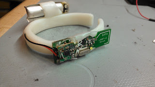
All of these functions are controlled by the bracelet. The bracelet has the other PCB that was on the board, which is basically just a PIC16F1824 with a radio module connector and breakouts. It sends data up to the glasses over the 2.4GHz link based on input from two buttons and the 3-axis accelerometer. This is all powered by a tiny 70mAh lithium ion cell. All of these components are attached to a nylon watch band with hot glue. One of the switches on the bracelet advances color mode, and the other advances brightness mode.


In the end, I couldn't be happier with how these came out. I have to fight the urge to wear them everywhere all the time. Thanks for reading this extremely long post; you can see more pictures of these if you scan the crowd in pictures from Raleigh-area EDM shows in the coming months:


Here's the code for the glassesand the controller.

Thursday, July 11, 2013

LED Glasses


Here’s another example of a totally useless project that I took on with no justification other than “because I can.” I love lights. At EDM shows, everybody loves lights. After going to my first Bassnectar show I decided I had to make some kind of wearable lighting system to wear to future shows. Not wanting to spend infinity hours stitching LEDs into clothing, I settled on LED glasses. Just lighting up isn’t enough though—they had to be painfully bright and do some cool effect that can complement music. 

On a long drive last year I thought of an idea for this—just pulsing lights to the music has been done before, but what about making the lights respond to body motion as you move to the music? The idea solidified as an accelerometer to measure hand movement which would control the brightness of the LEDs. The accelerometer had to be mounted on my wrist and get signals to the glasses on my head, so I’d have to run wires along my arm. No way, using wires on a wearable system sucks, and I have a stack of uNRF boards waiting for good applications, so I went with 2.4GHz.

Hardware: The accelerometer I used was ripped from a Wii controller clone from ebay (which I bought just for the housing) and gave me three analog signals for X Y and Z. Both transmit and receive sides would use my uNRF board with a nRF24L01+ and PIC16F1824. The LED driver is a MAX16820 3-Amp buck converter that takes a PWM control signal. The LEDs are just a ton of whatever I have lying around wired in parallel (because sticking high voltage on my face is where I draw the line).


Software: I already had basic code running on my uNRF boards to send and receive, so the radio link was taken care of. I went through a very interesting design process with regards to the signal flow from accelerometer to LEDs. In my initial exploration of the idea, I programmed one microcontroller to handle the entire process from reading acceleration data to outputting the LED PWM signal. I wanted the system to work regardless of orientation of the accelerometer so I set up the software to sample all three axes. 

The system only needed to respond to fast movement, so I wrote an algorithm that calculates a long-term (10-second) moving average for each axis and then calculates the absolute value of the difference between the instantaneous reading and the long-term average. These values for all three axes are summed to create a single value that represents total movement in the short term. This value is then fed into two processes that generate the PWM output. 

In order to create an effect that looked good, I wrote two independent processes that increase and decrease the PWM duty cycle. The increaser increments PWM any time the scaled movement value is greater than the current PWM value, and the decreaser decays the current PWM value at a steady rate. These two processes are triggered by timers that run in the interrupt service routine so they can each be configured to operate at different speeds. The values I settled on run the increase at 1000Hz and the decrease at 250Hz. 

All those processes working together created the whole signal flow, but I had to cut it into two sections separated by the radio link. To do this, I picked the point in the flow with the lowest bandwidth, which ended up being the total short-term movement value. This value is calculated in real time by the microcontroller on the wrist unit and then transmitted at 50Hz to the board on the glasses. The micro on the glasses takes the movement value and handles the PWM increase/decrease and outputs it to the buck driver. 

The final software pieces were some modes which I could switch by pressing a momentary switch on the glasses—I included motion control, lightning mode, strobe mode, and constant brightness. Lightning mode is a really fun one where the LEDs sit at low power and then pulse at full current for 50ms any time the accelerometer reads over a certain threshold; this gives a really cool effect of being able to throw lightning strikes. I also included the ability to scale down the brightness in all modes to 50%, 25%, or 12% (in case people at clubs yell at me).

Here’s  a preliminary software test before any hardware was built:


Build: I found some really cheap cool-looking sunglasses and started building the LED array. This involved a totally insane process of soldering 60 XB-D LEDs directly onto two strands of 30AWG bare wire, which I do not recommend. Nor do I recommend throwing that away and repeating the process with XQ-B LEDs when LED issues appear, and I certainly don’t recommend trashing that and building a third array with color XP-C LEDs. But yes that is what I did. 


When I had to build the array for the third time I decided to switch to a color instead of white and settled on green, so the final product used 56 green XP-C emitters. I build the array in two sections and laid them onto the glasses frame with hot glue. The technique I used was to lay dabs of hot glue on the plastic frame, lay down the leds (shaping by bending the wire between emitters), and then heat the LED strip with the soldering iron to melt the glue.


With LEDs down, the rest of the glasses build was just mounting the uNRF board on one side and the MAX16820 board on the other. I put together a simple 2S1P battery pack out of IMR 18650 cells with a long cable and a connector to power the system. Assuming an average of 50% brightness (certainly an overestimate), the pack should give me 2.9 hours of runtime.


The wrist unit was made from a uNRF board, the accelerometer board, and a small lithium polymer battery (which should last approximately forever at an average current draw of 1.3mA). To make it actually stay on my wrist and be removable, I made a bracelet out of shapelock to which all the components mount.


Here are some complete final system tests:


Here’s the software for the transmitter and the receiver.

Sunday, April 28, 2013

UAV part 5: Switch to V911


Just when I started to make progress on my overvolted single-rotor helicopter, the tail motor blew up (as I knew it would). To move forward, I could have gone back to Syma S107s, but I’m starting to dislike the mechanical complexity of the coaxial system. I have a few of the WL Toys V911 helicopters and they’re awesome. Once you get a controller, you can buy the helicopters for $20, which is actually cheaper than the S107. The V911 is bigger, faster, and has more excess lift than the S107, and weighs in significantly lighter:


I stripped down one of my V911s to install a MATH board. There was no good place to mount the board so I made a 3D printed bracket that screws into the posts where the stock PCB attached. The bracket also has a tray to hold the battery. After I mounted everything, I found that the CG is too far forward. I’ll have to reposition the battery later to fix it, but in the meantime the V911 includes an easy way to compensate for this – the swashplate.


I plan on using the pitch control eventually, but for now I needed to lock the pitch and roll. I used pieces of music wire and bent them into links that connect the swashplate control horns to some studs on the frame. I intentionally left them too long so I can make adjustments by slightly bending the wires to reduce the length. This gives me pretty precise control and I was able to adjust everything into balance.
  
Then I had some weird issues with a lack of power from the rotors. I checked my PWM output on the scope and tested 4 different batteries (including the stock V911 battery) with no success. Eventually I figured it had to be my FETs, so I salvaged the motor FETs from the original V911 board and put them on my board, and that fixed it. I’ve never had issues with the FDN5630s that I always used on these boards, but this motor is higher current. Another difference is that on my first single-rotor I had higher voltage on the digital section so the FETs had a higher gate voltage to work with, so they may not have been saturated when I tried it here.


 I started with the same code I had used on my smaller single-rotor, and it held yaw immediately, but with some oscillations which you can see in the video. It’s very promising that the PID loop is transferable to a completely different physical system. I just need to make some adjustments to the gains now to get this one locked in. After that I’ll start on altitude control. I did a quick lift test by taping an ultrasonic rangefinder board to the helicopter to see if it could lift it. It could, but just barely. I’ll have to come up with another altitude sensing solution. I may just have to buy one of the more expensive rangefinders that use the single transducer.


I made some other progress towards helicopter autonomy this week—I got the optical mouse sensor working. The one I found in my junk bin was an Avago ADNS-1620. This part had no available documentation, but I did find a lot of similar parts with identical pinouts. They all have the same serial communication protocol, but some lunatic at Avago decided to put the same registers at different addresses in each variant of the sensor. I went through datasheets one by one and punched in new addresses until I found a set that worked. They came from the ADNS-2620 datasheet.

I now have the sensor reading out x and y movement, as well as a “surface quality” value, which is an indication of how good the focus is. I found that this value tracks the distance from sensor to surface with exact repeatability and plenty of modulation in the value as you move around near the target height… Yeah, that’s a free altitude indicator using a sensor that I was already going to include! The downside is it’s only for one specific altitude (whatever I choose as the focal distance with the replacement lens I find), but I think it’s a viable option. I may attempt that as an intermediate step before working out the weight issues with ultrasonic. Wouldn't that be cool to detect altitude based on the focus of the image of the ground?! This method has another significant drawback: if the helicopter goes high enough above the focal distance that it can no longer recognize the correlation of increasing height to decreasing image quality (because the image quality is equally low for different heights so far from the target), then it could just keep going up. Luckily I don’t have to worry about such things any more since I have the radio link, so I can experiment with it freely.

No code in this post, it’s still the same software as last time. I’ll upload a new one once I pull my mouse sensor functions in. 

Saturday, April 13, 2013

Veloster Console Lighting


Here's the first of what I hope will be many posts about modifications to my new car, a Hyundai Veloster. I have a long list of ideas for things I want to do with the car and I thought this one was a good starting point. The car has a little tray under the dash directly in front of the shifter where I usually keep my work badge and other small things. I thought it would be a nice addition to have some lights illuminate the tray, but they would have to turn on and off automatically so they're not distracting while driving at night. There are some plastic handle-type things on either side of it, so I planned to put a beam break sensor across those to trigger the lights when someone reaches in.

Here's a schematic for the circuit I designed. It's run by a PIC12F615 and has an IR led and phototransistor for the beam, a 5V regulator, and three white LEDs driven by a MOSFET. After getting the dash open I discovered a good way to include a programming connector so that's included as well.
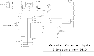
The software for the microcontroller operates the beam break sensor entirely in interrupts, and the main loop interprets that information and loads brightness levels into the PWM peripheral. The algorithm for the beam detection is a technique I've used before (in Tiny Tank Bot, among other things): the infrared LED is toggled on and off, and I take an analog measurement from the phototransistor in each state. The two values are then compared to see if they differ significantly, which indicates that the IR light from the LED is "visible" to the phototransistor. This technique works well to reject varying levels of visible light (and other sources of IR) that influence the reading from the phototransistor. Repeated comparison results are then accumulated in a counter so that a confirmed detection of the beam requires a number of consistent positive results. The duty cycle of the IR LED is kept low to save power. 

The brightness levels for the white LEDs are taken from a logarithmic table, and I played around with a variable timing technique on the ramp up and down until it looked smooth. I have the LEDs stay on at 1% while no objects are detected so there will be a nice glow on the tray. The software ramps up the brightness to maximum as soon as the beam is broken, but it waits for the beam to come back for 1.5 seconds without interruption before dimming back down. This makes the lights stay up for as long as you're reaching into the tray, and then smoothly go back down when you're done. Here's a software test on the breadboard:


Once the software and circuit were proven out, I built the circuit on perfboard. I left the IR LED and sensor on headers so I could disconnect them to make installation easier. 

Here's a test of the completed circuit:
 

Next step was the scary part: disassembling my dash. Luckily I found some instructions from a Hyundai service manual posted on a forum. The center piece of the dash that holds climate controls and two vents is held in by friction clips and can be pried off with plastic tools ( I made some from lexan stock I had on hand).
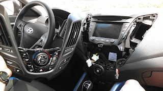
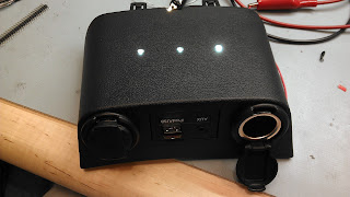
With that piece off there's plenty of room to work in there, and you can see straight down to the piece above the tray (which has the 12V outlets, aux input, and USB port). I could then see how to get that piece off: it's held in by the same type of friction clips, and it just slides straight out towards the shifter. There is a slot to put a (very short) flathead screwdriver in the back to pry it off. If anyone wants to reproduce this, you don't have to take off the climate control piece, just slide that little pod straight out until the clips pop off. I took that piece in to my workbench and prepared an LED board with three cool white XP-Gs. I drilled holes for the LEDs in the plastic and stuck the LED board down with VHB tape. 
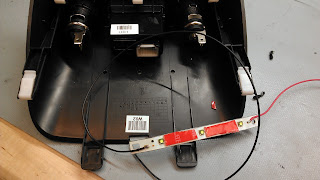


The rest of the circuit went in next. It steals power from one of the 12V outlets, which means this is only active while the car is on. This is not ideal--it would be nice to have it on when you first get in the car and for a short time after turning it off, but this way I can be sure I don't make a mistake that kills the battery while it's parked. I could connect it to a 12V line that's on all the time as it only draws 2-3mA in the idle state, but I didn't want to run new wires to this area. 
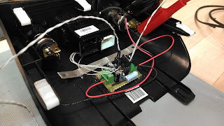

At this point I noticed that the 12V outlets have little cutouts in the metal cylinder that are just big enough to pass a 0.1 header (pin strip) through, which gave me a perfect way to include a programming connector. I wired in the connector and insulated it with electrical tape. I then close the lid on the 12V outlet and it's completely hidden, but I still have the opportunity to update the code if I think of a change I want or if my parameters don't work anymore in the real application. Also, the signal from the phototransistor is shared with the data line, which may help in debugging since I can put it on a scope without taking anything apart. 


The outlet isn't usable like this, but that's unlikely to be an issue any time soon since there are two of them. Once I'm sure that I'm happy with the software, I can just push the connector up into the cavity and then the outlet will be usable again. Here's a test after everything was installed onto the plastic pod:


After I got to this point, I went back to the car and spent a whole bunch of time trying to get the plastic handle things open so I could install the two parts of the beam sensor. I didn't make much progress, and decided that it was silly to waste any more time on it when I could just change the sensor from beam break to proximity. Beam break would have given more reliable signals, but changing to proximity allows me to install all components onto a single piece of the dash, not run any wires, and also hides the sensor components from view. 

The change to proximity is almost as simple as inverting the logic in the software: turn the lights on when the IR beam is detected instead of when it goes away. In reality I also had to make some tweaks to increase sensitivity and chose a different phototransistor that performed better in that arrangement. You can see both versions of the software at the bottom of the post. After those changes, I drilled two small holes in the bottom of the plastic piece and stuck the IR sensor and emitter down there. The great thing about this location is that it's pretty much impossible to get your head low enough in the vehicle to see the bottom of this piece, so none of the modifications will be visible. 


Here's a final test of the electronics before being installed in the car:


Installation in the car was very easy, just pop the pod back in and plug in the connectors. Here's a camera shot from below where you can see the mods, but you can't see these while you're sitting in the car. 


And from the video at the top, you can see it works very well. So far it's properly detected my hand every time I reach into the tray, and I'll be watching to make sure I never get any false detects while I'm driving which would necessitate a code tweak. 

Here's the original beam break code and the final proximity code

Bonus project: 
While I had the climate control piece out, I decided to swap some LED colors just for fun. I changed the passenger airbag indicator from orange to blue (this one always bugged me because most of the other indicators are blue), and I changed the seat heat indicators from both orange to orange and red to indicate low and high heat levels. 


Saturday, April 6, 2013

UAV part 4: single rotor


This is the helicopter I’ve been working on for the long period since my last post. After I got the coaxial helicopter up and running with my custom electronics, I flew it way too high outside and crashed it hard enough to break the plastic frame. Then I flew it without the frame like this:


That left the drive gears on the bottom exposed, and I broke one of the gears in another crash. That left all the mechanics pretty much useless, until I had the crazy idea of converting it into a single-rotor helicopter since I still had one working drivetrain.

The board I used for this one is a custom helicopter board I’d been designing for a while. This board put all the electronics I used on the 2.4GHz coaxial into a single PCB, but with a more capable microcontroller to allow for more functions. The board features are:
·         PIC16F1829 microcontroller
·         nRF24L01+ 2.4GHz radio transceiver
·         LY550ALH single-axis gyroscope
·         3 N-channel motor FETs
·         Breakouts for connecting ultrasonic rangefinder & optical sensor


This board is called MATH, for Mostly Autonomous Tiny Helicopter (although at this point it stands for Mildly Autonomous). The core functions are just to get me up and running on a helicopter with the radio link, but later I’ll connect in the ultrasonic rangefinder for altitude control and make it really autonomous.


The connections for the optical sensor (labeled “terrain imager” in the schematic) are for an idea I had that’s not yet tested: I have seen a few robotics projects where people used optical mouse sensors to keep track of motion by focusing them on the ground below the robot. I think it will be possible to use this technique on a helicopter provided I can find optics to focus the sensor on the ground at a height of 3 or 4 feet (and maintain altitude precisely). If this works, the helicopter could keep track of its path and position and navigate autonomously with high precision.


To make the single rotor helicopter, I stripped down the Syma S107 to minimal weight and removed one of the drive motors, gears, and rotor. The tail rotor is now needed for torque balancing so it has to aim sideways. Early tests showed that the stock motor wasn’t powerful enough for this job, so I make a custom tail boom to extend it and increase torque without increasing power draw. I later replaced this aluminum boom with a carbon fiber boom, and put a bigger propeller on the tail motor.

I was able to make the single-rotor fly, but it had to be stripped to less than 20g and run at full power just to stay aloft. Clearly I needed a bigger motor for the main rotor, but I decided to do something crazy just to make this one work, and went to a 2-cell battery to double the voltage. Now I don’t have to worry about weight so much and have power to spare. Unfortunately the motors get hot as hell and will probably burn out very soon, but for code development purposes this setup works well.

I started from scratch on the software to run this helicopter to keep everything clean. I struggled for weeks trying to stabilize the helicopter with my yaw control loop, and finally found the solution this weekend. I was using PID all along but could never seem to get my gains right, but then finally discovered that the control loop was being screwed up by noisy readings. The solution was to use a 100ms moving average (4 samples at 25ms) to get the yaw value from the gyro, and then derive the integral and derivative terms from that value. That smoothed things out and it finally stabilized.


It still jitters right and left, so there is more work to do. Once I’m happy with this I plan to work on adding a magnetic (non-contact) swashplate mechanism to this helicopter to control pitch. Here’s the code