Wednesday, October 24, 2012

Super RGBWUV flashlights


Shortly after I first got my hands on an MC-E color, I built an RGBW flashlight using this Romisen host. I designed these just to be fun to play with, but they can still be practical as well. The first one used a 7135 driver board with most of the traces cut and the PIC hand-wired. This was the light where I first developed my novel method for switching modes on brief power losses. Since then the RGBW lights have been evolving, including some custom driver boards I had manufactured.


They still use the 350mA 7135 regulators, and the most recent board uses the underside to double current to 700mA per die. My most recent iteration of the light includes an ultraviolet LED, which is run by a single 7135 regulator that’s hand-wired and floats above the PCB. I've also switched to XM-L color. The software that runs these has gone through a lot of iterations for different light configurations (including my monster RGBW). It includes battery monitoring based on using ADC to read an internal voltage regulator, which is indicated by brief flashes of red regardless of mode.


Today I made a significant upgrade to the software to add more modes. Because the goal of these lights is to have one that can do everything, I’ve adopted the policy of never removing modes as the software is developed—only adding them. That’s why this current revision of the code has 19 operating modes, which are:


  1. high white
  2. low white
  3. ultraviolet
  4. color fade
  5. color freeze
  6. stunner
  7. annoyer
  8. all on 20%
  9. firelight
  10. police lights
  11. red
  12. green
  13. blue
  14. red safety flasher
  15. red beacon
  16. 30Hz white strobe
  17. 14Hz white strobe
  18. 4Hz white strobe
  19. white beacon


Here’s a video of the light demoing the modes:


Here’s the code.

Ultimate Flashlight Code


For quite some time I’ve had two lights that use a really cool mechanical arrangement called Piston Drive that allows the light to have a switch at the back of the body that is a momentary switch connected to the driver instead of interrupting power to the whole light. My two lights are the Nitecore D10 and EX11. Sadly they’ve discontinued these lights since I bought them. Piston Drive is really cool, but I found that I never really used the lights because I didn’t like the way they were programmed. Well that has gone on long enough…

Modifying these two was a good opportunity for me to finally put into writing all of the ideas I have had over the years for flashlight firmware. I have always really liked the user interface on Novatac and HDS lights, so many of my ideas are stolen from their user interfaces. There are things about those lights that I wanted to change, though, and some new features that I would like. I also know some people that I will be sharing this code with who have their own preferences, so I wanted configurability. After a lot of thought I settled on this poorly-written description:

features
smart momentary
tactical momentary (reset by power cycle) w/ selectable mode
logarithmic level ramp
configurable, NVM-saved primary mode
novatac-style shortcuts to max (from on and off)
randomized strobe
emergency beacon mode
locator beacon mode
configurable strobe (?)
battery level monitoring(? this would require automatic detection of cell type)
temperature monitor & protection

required microcontroller features
NVM
software-configurable WDT
PWM
ADC
internal Vref for ADC (?)

pins
1,2 power
3 PWM
4 temp ADC
5 temp divider supply
6 switch
7 battery voltage monitor

UI

on power up, read in NVM, including user-configured primary mode, set it to current level. enter standby
in standby: if configured for locator beacon, set WDT and sleep, waking to flash beacon. else sleep with 
only wake source as switch. wake on switch change
wake: immediately output current level. measure press time to determine whether to latch on 
(smart momentary). long press: stay on in momentary, return to standby when released
short press: latch on at current level. if switch is pressed again within double click time, 
go do second press action
second press action: immediately output maximum. measure press time. short press: latch on
at maximum. long press: momentary maximum, return to standby when released
all momentary modes override temperature protection

while on: if switch is pressed, take no action immediately and measure press time. long press:
begin ramping brightness. if current level is <10%, always begin ramping up; if level is >90%, 
always start down. between 10% and 90%, ramp in the opposite direction of the previous ramp action, except 
that the first direction in any new session is down because there is no shortcut to low levels.
short press: turn off and wait for subsequent presses. if none, enter standby. if pressed again,
turn on again at last level and measure press time. short press (double click): go to primary mode
long press (click press): go to maximum mode
after double click monitor for further clicks. a triple goes to strobe mode. in strobe mode, functions
are similar to normal -- on and off are the same including momentary. double click or click-press to get 
back to normal modes. a press and hold (ramping command) changes to other special modes (so far just beacon
strobe). triple clicking while in strobe goes to configurable strobe mode

a quadruple click from on enters the setup menu
setup menu:
similar to novatac. click to advance to next option. press hold to activate an option
first option is tactical momentary. shows a single blink to indicate.  
once activated, output will be momentary only, in the last used light level (or strobe).
second is set primary level. indicate by double blink. when activated, it will store the last used 
level as the primary mode. 
third is locator beacon, indicate by blinking dimly like the locator. activating this will toggle 
locator on or off
fourth is force momentary to max. indicate with a long blink. if activated, all smart momentary outputs
will be at max level instead of last used level

configurable strobe(TBD):
config strobe is a one-time function, so double-click commands will go back to normal mode. on/off won't
work because single click has been reassigned. power cycling can also be used to go back to normal.
if double-click is used to exit, strobe settings are maintained and they will be the initial state the 
next time config strobe is entered. a ramp command changes the speed or duty cycle, and a click toggles 
between adjusting speed and duty

It turned out that planning the functions was the most difficult part. I wrote it for the PIC12F1822,  which is Microchip’s newest 8-pin part. Since µC cost is not a deciding factor for such a project, I had no reason to use anything other than the most capable micro I had available. After I had a complete plan, coding and debugging the software only took a few hours. Understanding the D10 and EX11 drivers, however, was fairly complicated. Both of them had an 8-pin microcontroller on the driver to control the output. The EX11 had a clearly marked PIC12F683 running it (a great choice of microcontroller; if I had known this one was on there I would have developed my code on the same part so I could just reprogram instead of replacing it). The D10, however, had some weird chip on it with power pins in non-standard locations and the markings were scraped off.

Both drivers use boost to generate power for the microcontroller from battery voltage. The EX11 has to be buck-boost to accept rechargeable cells, and I suspect the D10 is also. I really only investigated the aspects that were critical to developing the application firmware, though. Both lights use some kind of regulator to drive the LED that is controlled (or maybe just switched) by a PWM signal from the micro. The D10 is simple, it’s just switch input and PWM output, with a fairly fast pwm at 31kHz. The EX11 is more complicated as its PWM has a narrow range of 41% to 75% duty from min to max, and it has an extra output from the microcontroller to enter a low power mode in standby.


After working out all these hardware details by scoping the existing chips and then breaking out connections to my protoboard, I finalized code and installed my own microcontrollers. On the EX11, the chip is a direct replacement. On the D10, the new chip is floating and the four connections are wired into the old chip's pads. 


I have a version of the code for each light, and the EX11 version has an extra setting in the configuration menu that turns off ramping and uses 4 discrete levels. Here’s a video showing the user interface:


Code is here: D10 EX11. It’s my hope that this can easily be applied to many different lights (as I will be doing soon) so that other people can use it.

Saturday, October 6, 2012

UAV part 2: radio control


UAV progress had slowed for a while, especially during the 3 weeks I spent in China (but that’s ok because I bought another helicopter while I was there). Since I came back to the US, I’ve been working on this unit, which I’m calling sAAV (semi-Autonomous Aerial Vehicle):


 The motivation to pause work on the yellow heli and switch to this came from a number of places:

1. I discovered the source of most of the problems with the yellow helicopter: the ultrasonic rangefinder boards I was using function above 4.1V, but not below. Every time I ran some debugging code to indicate the altitude readings, everything looked great. Then I would load code that actually flew, and the battery would droop below 4.1V, and all my altitude readings would be garbage. Conclusion: the ultrasonic boards must be abandoned, and I have to do altitude sending from scratch
2. Following rule #2 of Everett’s rules for tiny autonomous helicopters, I have to add a radio. Might as well make it 2-way communication so I can actually debug things instead of just guessing what’s going on
3. Autonomous vehicles are fun, but I also like remote-controlled ones

So I drew up some boards that include Nordic 2.4GHz radio modules and ultrasonic transducers. I also realized that on my previous board iterations, I had devoted nearly 50% of the board space to an H-bridge for the tail rotor, but it really isn’t important to be able to travel backwards. Certainly not worth the board space (and weight) I was devoting to it. That’s how I came up with this board:
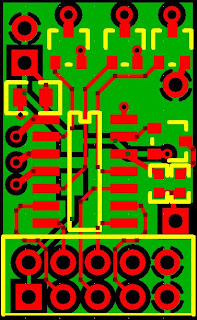

The processor is PIC16F1824 like the last few versions. It includes everything this project needs – SPI for the radio, 4 independent PWMs, EEPROM, ADC, and more than enough code space. The 10-pin header goes to the Nordic nRF24L01 radio module. The only (populated) hardware other than the PIC and decoupling cap are three MOSFETs, one each for CW rotor, CCW rotor, and tail rotor. The stuff on the right were some guesses as to what I might need to operate an ultrasonic transducer. Since I ordered these boards, my testing has shown that ultrasonic distance measurement can’t be done without amplification on the received signal, so I won’t be populating those components.

Because of physical space restrictions, I didn’t end up connecting the radio module with the 10x2 header like this:


Instead I wired it in at 90 degrees so I could put it down inside the frame where the stock board was. I also cut off the trace antenna and added a full-wave wire whip antenna:


My first try at the code to operate the vehicle went like this:
Wait for a packet from the radio
No packet for 4 seconds? Turn off rotors
New packet:
Load throttle value out to main rotors
Load pitch value onto tail rotor
Retrieve trim value from EEPROM based on current throttle value
Skew power to main rotors one way or the other based on trim value
Skew power to main rotors one way or the other based on yaw value
Adjust stored trim value in EEPROM if the packet contains an adjustment

My big innovation was storing 16 different trim values instead of one. I learned from flying these helicopters in their stock configurations that as soon as you got the trim set right,  you’d change the throttle and your trim would be wrong again. To fix that, my code stores an independent trim value for each 1/16th of the throttle range.
The controller is the second version of my tiny transmitter, which was first used with the RC buggy:


The new version of the PCB includes some indicator LEDs, through-holes to mount the battery holder, and gives the microcontroller the ability to switch off power to the high sides of the potentiometers in the joystick. This means it can go to sleep in the off state instead of needing a hardware switch.

Since I want all my RC vehicles to be operated by this one controller, I had the extra challenge of operating a 3-channel helicopter from a single x/y joystick. The throttle and yaw obviously take priority, so those are mapped to stick y and stick x. Pitch isn’t as time-critical, so I have the controller toggle the tail rotor on (25% duty) and off every time the joystick is clicked in. The last command that needs to be sent is trim adjustments. To make trimming a bit more intuitive and to save hardware, I came up with this scheme: while flying the helicopter, I compensate for trim issues by steering right or left with the joystick. Then I press the trim button, and the controller sends a command to the helicopter to adjust trim in the direction that the joystick is currently pushed.
After the first flight, I read out the EEPROM trim values to see how they looked. The trim at all throttle levels was fairly similar, clearly compensating for the added drag of the gyroscopic stabilizer on the top rotor. The first flight also showed me that actively controlling the throttle with this small joystick makes hovering very difficult. The next iteration made joystick movements adjust the throttle level up and down, instead of the throttle level tracking the joystick position. After all these changes, I got the vehicle to the point where I could actually fly it, but yaw trimming just doesn’t work. I can spend a bunch of time getting the yaw trimmed just right, and it will hold a heading for a few seconds, and then just start spinning. Then I finally figured out what the mystery component on the daughter board in the stock electronics is:
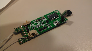


MEMS GYROSCOPE! I couldn’t believe a gyro could be so cheap that it’s included in a $20 helicopter, but it is. I figured out the component’s function by putting its output on the scope and moving the board around. It’s clearly a gyro and not an accelerometer because the signal tracks rotational speed through the entirety of a rotation (including when the rotational acceleration is zero), instead of showing the start and end of the rotation as a rotational accelerometer would.
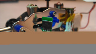

I pulled the gyro off and wired it into my board. I rewrote most of the yaw control code since I’m now taking yaw adjustments from three sources (trim value, controller command, gyroscope) and included adjustable gain coefficients for each term. To my amazement, the first time I flew with the gyro on board, it actually started correcting for yaw drift! But the gain was way too high, leading to oscillations that eventually go unstable. Since the gyro signal’s zero level changes with input (battery) voltage, I maintain a long-term moving average of the signal and then get my current reading my comparing the instantaneous to the long-term.
I then spent way too long tracking down a problem with the radio (turns out you have to read out the RX FIFO buffer even if you don’t want the data, or the radio will start rejecting incoming data and never tell you it has new packets). My debugging work is all done on this proto-board replica of the helicopter electronics:


Working with this setup also showed me the presence of a really dangerous bug: if the radio dies, the MISO line goes high, so all bytes received over SPI are 0xff. This means host software will always think the flag indicating new data is high, and all the new data will 0xff. Because of the way I have my control values encoded (the simplest way), this means that if the radio dies, the helicopter turns all rotors on maximum (and turns right) (and adjusts the trim value left) and never registers that the radio link has died. Yeah, that was one loose wire away from a fourth helicopter flying off into the sunset never to return. Now I recognize the 0xff values and interpret them as a loss of radio link.
Now that I have the gyro working, I need to spend a little time adjusting gains to get flight totally stable. I'll put up a video when it flies better. Only then can I start working on full autonomy. On the side I’ve been working on using ultrasonic transducers to measure distance under my own software control (but yes, it needs active amplification on the receiving end). Won’t it be awesome to just set an altitude with the controller instead of having to constantly adjust throttle to hover!?
Also, this one uses the motor coils to play Ride of the Valkyries when it powers up. As all helicopters should.
Here’s the code that runs the helicopter and controller. It’s mostly unstable from the gyro measurements, but it’s almost there.