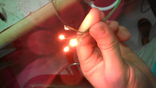
Saturday, December 22, 2012

Playstation controller


I had decided a while back that I needed to build a new, more capable controller for RC vehicles & robots. The goals were:
More buttons for various functions
More analog inputs than a single joystick
Operated with two hands
LCD display to show data sent back by the vehicle

I was about to start designing a board when I came across a PS2 controller. These can be found really cheap now that the PS3 has obsoleted them. Using these controller for robots is not a new idea, lots of people have done it, and they’ve put all kinds of information on the internet about how to interface with them. The controllers communicate with a form of SPI. It’s regular SPI except that the bit order is flipped to lsb first (where standard SPI is msb first). The protocol is close enough that I can use the built-in MSSP hardware in the PIC parts I’m using, if I do some data manipulation before and after exchanges. Thanks to all the people who have worked out the protocol and shared their findings, I got the controller working very quickly.


I wrote robot controller code for the PIC16F1516 (same as the one on the SAVIC board) that can talk to the PS2 controller, a Nordic radio, and a character LCD. The radio and the controller share the SPI bus, but they have different settings for clock polarity and data sampling edge, so I have to switch the MSSP settings before I activate each one with its slave select line. Later I’ll use the LCD to show data coming back from the vehicle, but for now it was just used to help me work out the bugs with the PS2 controller. It turns out the analog sticks on these give pretty messy readings, even with the genuine Sony controller. To counteract this, I’ve added a bunch of processing that the analog readings go through to center them and to apply a logarithmic curve to the output. The code can also poll the controller for which mode it’s in, so it asks you to activate analog mode before it does the centering and starts transmitting.

This first try worked out so well that I will definitely stick with the PS2 controller for robots moving forward. I’m currently working on talking to a graphic LCD so I’ll be able to display images from a camera on the vehicle. Once that’s finalized, I plan to build an add-on that attaches to the front of the controller that contains a battery, radio, LCD, and the microcontroller to operate them all.

Here’s the code for the robot controller.

SAVIC board


I finally got my Semi-Autonomous Vehicle Integrated Controller (SAVIC) boards in from batchpcb. I used this project to learn to use Eagle to do layouts; it’s my first Eagle board and my first batchpcb order. I set out to design the SAVIC board so that I could quickly and easily get moving with small robots instead of custom building new stuff every time I wanted to try something new. This board is meant to include all the features you’d need to get started on a small robot or RC vehicle, and intended to be modular so it can be expanded upon. SAVIC has:
2 H-bridges for DC motor control
2 high-current sinks for single-polarity loads with PWM
2 servo outputs
2 analog sensor inputs
2 digital (switch) inputs
RGB status LED
nRF24L01 2.4GHz radio
HC-SR04 ultrasonic rangefinder connection
SPI expansion connection
PIC16F1516


I managed to pack everything into a 1.5x1.6 inch board. I had learned something about H-bridges from the board I originally used on the RC buggy. The P-channel FETs in that design had their gates switched by the drains of the N-channel FETs, so they were directly connected to the load. That worked for very small motors (in my 6” helicopter), but when I put a bigger DC motor on it, the inductive spikes ruined it. For the SAVIC board, I used bipolar transistors to invert the gate drive signals for the P-channel FETs.

The only issue I had with the first one I assembled was voltage limitations on the peripheral devices connected to it. I designed it to interface to HC-SR04 ultrasonic rangefinders because they’re so cheap and easy to find, but they have crippling supply voltage requirements. They don’t really work outside of 4.5-5.5V, where the PIC can run from 1.8-5.5V. The Nordic radios can’t go higher than 3.6V (but luckily the signal levels can be higher), and servos need 4-6V. On the board I put a 5V regulator to run all digital devices except the radio, which has its own 2.5V regulator. Servos pull tons of current when they move so I didn’t want to load the 5V regulator with them, so they’re powered directly from input voltage (as are the H-bridges). The problem is if I power the board with 6V, the 5V regulator doesn’t have enough overhead so the digital supply isn’t high enough to operate the rangefinder. If I go higher than 6V input, the servos get overvolted.

 The next revision will have to fix this somehow (probably by ditching the HC-SR04), but for now I’m running the board from 2 Li-Ion cells (8.4V) and putting a small adapter for the servo with an independent voltage regulator on it. One big advantage of this setup is that it overvolts the drive motor on the buggy like crazy, which gives it awesome speed and power.

I’m trying to transition to only working in C for robots, so I rewrote most of the functions I had already written for other RC vehicles. It’s programmed to used the same radio packets as the helicopter so I can use the same controller for both. The code has drivers for both servo outputs, bidirectional pwm for one motor, talking to the radio, and rangefinding. Once I got it operating well under remote control, I added an autonomous mode that just wanders around and avoids crashing based on data from the rangefinder. Autonomous mode is activated by a button on the controller, so I can switch between RC and auto on the fly.

Here’s code for the SAVIC board. Controller code will be in the next post.

Saturday, December 1, 2012

UAV part 3: C code


Huge UAV progress in the last week. I had figured out that a gyroscope was needed for stable flight (that’s how the stock control boards do it) and installed a gyro on my helicopter, but I wasn’t getting anywhere on coming up with an algorithm that would accomplish stable flight. I kept working in my old source file which was written in assembly and was attempting to write very complex math with 16 bit values (actually 17 bit for some signed values) and it became totally unreadable. After years of working with PIC I reached the point where I couldn’t accomplish the goal without switching to a higher level language, so I set out one day to get things working with the C compiler.

I had been told by many people (including a Microchip FAE) that switching over to C would involve a whole lot of frustration in order to get the whole toolchain working, but it turns out they were full of crap. It was ridiculously easy, and in about 3 hours I had rewritten the entire helicopter source code in C and had it running. I keep running into bugs caused by the way the compiler handles math involving ints (16bit) and chars (8bit) (which I’m often forced to work with based on EEPROM hardware, radio packets, etc.), but once you solve a few you figure out the tricks to force it to work the way you want. Admittedly writing in C creates machine code that is bigger and slower than assembly, so for my cost- and/or time-critical applications (like the ones I write at work) assembly is still the way to go. However, for hobby projects like these, the cost of the processor is meaningless (even something ridiculously overpowered is generally under $1.50), so I have the freedom to run complex code on an awesome processor. Luckily (i.e. as planned) the 16F1824 kicks ass and can run huge amounts of compiled C with no trouble.

Once I got a version of sAAV v3 rewritten in C, I could do experiments and improvements way faster, so sAAVinC (semi-Autonomous Aerial Vehicle in C) evolved pretty fast and I learned all kinds of things about making machines like these fly. The code has now departed quite drastically from what the old assembly source was doing. I have it running a control loop based on the gyroscope reading at 10Hz, and polling the radio for new control packets at 4Hz. After a whole bunch of test flights I arrived at a gyro feedback control algorithm that’s awesome.

It has a proportional term based on a ¼ second moving average (4 readings) and an integral term at 1/4th the gain of the P term. I put in a slow decay on the integral term to counteract erratic buildup. I also do a long (5-second) period of measurements upon power-up to calibrate readings from the gyroscope to establish a baseline of what a rotation rate of zero looks like.

The gyro loop got so good that I didn’t need to do yaw trim any more. With no trimming in the code at all, the helicopter would spin for the first second of flight and then the gyro loop would figure it out and stabilize. To get it even cleaner, I started initializing the gyro integral term to an experimentally-derived value that compensates for extra drag on the top rotor. This initialization is done any time the rotors are stopped for any reason (before I did that, if I was flying and then landed (and possibly moved the heli by hand) and then started flying again, the gyro integral would have been building up the whole time so when I throttled up, only one rotor would getting power).

Another funny thing that happened is the gyro loop was so good that when I tried to send yaw commands, the gyro loop would see the turn as a disturbance and compensate for it, aiming back to the heading it started at. My solution was to remove the yaw command term from the rotor output calculation completely, and instead inject it into the calculations for the gyro P and I terms. Effectively what this accomplishes is: when a yaw command is sent, it makes the gyro loop think the vehicle has turned in the opposite direction, so the gyro loop does its job and counteracts it by turning in the direction the pilot wanted.

In order to make the controller more generic (to use with other vehicles), I moved the math that interprets joystick inputs over to the helicopter. Now, the controller essentially just sends the stick position and button information and the vehicle decides what it means. I’m still doing the same throttle algorithm where pushing the stick up and down adds or subtracts from the current throttle value at increasing intensity as the stick is angled farther from center. I also wrote an update for the controller that puts it into sleep mode so I don’t have to pull the battery when I’m done using it. The last control update was to have the helicopter gradually change to new pitch values (on the tail rotor) instead of changing instantaneously. This came after I kicked on the tail rotor while turning and caused the helicopter to roll and crash spectacularly, breaking the tail fin and tail rotor. Now, when I click the joystick in to toggle forward movement, the tail rotor speed gradually ramps up over a period of about 3 seconds.

The other items I put in the helicopter code are a low-power standby mode and some tones (played on the motor coils) to indicate things like power up, gyro calibration complete, paired with controller, loss of control link, and entering standby.

So now I’m at the point where I have control that’s just as good as the stock helicopter, but running on completely custom code and using a 2-way 2.4GHz radio link instead of infrared. The next steps are to build a more involved controller that will be better able to help develop autonomous functions, and to install ultrasonic altitude sensing on the helicopter. My weight is currently at 39g (stock weight is 42g). I plan to put double-capacity battery on that will bring the weight to 43g, and when I add ultrasonic I’ll strip down more of the metal framework to keep the weight at or below stock.

Here’s a video showing how good the control is. As far as I know, this is now the only Syma S107 in the world that is radio controlled, meaning I don’t need line of sight and I can fly outside in sunlight, which I’ve been wanting to do for so long. The second video shows an outside flight, which is fun because there’s nothing to crash into but difficult because the slightest breeze just carries it away. As you can see, the range on the radio is more than enough to fly so far away that you can’t see it well enough to fly anymore.


Here is the most recent code for the helicopter and the controller.

One more thing: if you have one of these helicopters, take the yellow USB battery charger and throw it in the garbage. I discovered recently that it significantly overcharges the lithium cell, leading to extreme danger of explosions and fire. It actually blew up two small hobbyking cells that I tried to charge with it, after it pushed the cell voltage up to 4.6V. Do yourself a favor and buy one of these chargers (but you should probably replace R2 with something around 5k to set a safe charge current).

Wednesday, October 24, 2012

Super RGBWUV flashlights


Shortly after I first got my hands on an MC-E color, I built an RGBW flashlight using this Romisen host. I designed these just to be fun to play with, but they can still be practical as well. The first one used a 7135 driver board with most of the traces cut and the PIC hand-wired. This was the light where I first developed my novel method for switching modes on brief power losses. Since then the RGBW lights have been evolving, including some custom driver boards I had manufactured.


They still use the 350mA 7135 regulators, and the most recent board uses the underside to double current to 700mA per die. My most recent iteration of the light includes an ultraviolet LED, which is run by a single 7135 regulator that’s hand-wired and floats above the PCB. I've also switched to XM-L color. The software that runs these has gone through a lot of iterations for different light configurations (including my monster RGBW). It includes battery monitoring based on using ADC to read an internal voltage regulator, which is indicated by brief flashes of red regardless of mode.


Today I made a significant upgrade to the software to add more modes. Because the goal of these lights is to have one that can do everything, I’ve adopted the policy of never removing modes as the software is developed—only adding them. That’s why this current revision of the code has 19 operating modes, which are:


  1. high white
  2. low white
  3. ultraviolet
  4. color fade
  5. color freeze
  6. stunner
  7. annoyer
  8. all on 20%
  9. firelight
  10. police lights
  11. red
  12. green
  13. blue
  14. red safety flasher
  15. red beacon
  16. 30Hz white strobe
  17. 14Hz white strobe
  18. 4Hz white strobe
  19. white beacon


Here’s a video of the light demoing the modes:


Here’s the code.

Ultimate Flashlight Code


For quite some time I’ve had two lights that use a really cool mechanical arrangement called Piston Drive that allows the light to have a switch at the back of the body that is a momentary switch connected to the driver instead of interrupting power to the whole light. My two lights are the Nitecore D10 and EX11. Sadly they’ve discontinued these lights since I bought them. Piston Drive is really cool, but I found that I never really used the lights because I didn’t like the way they were programmed. Well that has gone on long enough…

Modifying these two was a good opportunity for me to finally put into writing all of the ideas I have had over the years for flashlight firmware. I have always really liked the user interface on Novatac and HDS lights, so many of my ideas are stolen from their user interfaces. There are things about those lights that I wanted to change, though, and some new features that I would like. I also know some people that I will be sharing this code with who have their own preferences, so I wanted configurability. After a lot of thought I settled on this poorly-written description:

features
smart momentary
tactical momentary (reset by power cycle) w/ selectable mode
logarithmic level ramp
configurable, NVM-saved primary mode
novatac-style shortcuts to max (from on and off)
randomized strobe
emergency beacon mode
locator beacon mode
configurable strobe (?)
battery level monitoring(? this would require automatic detection of cell type)
temperature monitor & protection

required microcontroller features
NVM
software-configurable WDT
PWM
ADC
internal Vref for ADC (?)

pins
1,2 power
3 PWM
4 temp ADC
5 temp divider supply
6 switch
7 battery voltage monitor

UI

on power up, read in NVM, including user-configured primary mode, set it to current level. enter standby
in standby: if configured for locator beacon, set WDT and sleep, waking to flash beacon. else sleep with 
only wake source as switch. wake on switch change
wake: immediately output current level. measure press time to determine whether to latch on 
(smart momentary). long press: stay on in momentary, return to standby when released
short press: latch on at current level. if switch is pressed again within double click time, 
go do second press action
second press action: immediately output maximum. measure press time. short press: latch on
at maximum. long press: momentary maximum, return to standby when released
all momentary modes override temperature protection

while on: if switch is pressed, take no action immediately and measure press time. long press:
begin ramping brightness. if current level is <10%, always begin ramping up; if level is >90%, 
always start down. between 10% and 90%, ramp in the opposite direction of the previous ramp action, except 
that the first direction in any new session is down because there is no shortcut to low levels.
short press: turn off and wait for subsequent presses. if none, enter standby. if pressed again,
turn on again at last level and measure press time. short press (double click): go to primary mode
long press (click press): go to maximum mode
after double click monitor for further clicks. a triple goes to strobe mode. in strobe mode, functions
are similar to normal -- on and off are the same including momentary. double click or click-press to get 
back to normal modes. a press and hold (ramping command) changes to other special modes (so far just beacon
strobe). triple clicking while in strobe goes to configurable strobe mode

a quadruple click from on enters the setup menu
setup menu:
similar to novatac. click to advance to next option. press hold to activate an option
first option is tactical momentary. shows a single blink to indicate.  
once activated, output will be momentary only, in the last used light level (or strobe).
second is set primary level. indicate by double blink. when activated, it will store the last used 
level as the primary mode. 
third is locator beacon, indicate by blinking dimly like the locator. activating this will toggle 
locator on or off
fourth is force momentary to max. indicate with a long blink. if activated, all smart momentary outputs
will be at max level instead of last used level

configurable strobe(TBD):
config strobe is a one-time function, so double-click commands will go back to normal mode. on/off won't
work because single click has been reassigned. power cycling can also be used to go back to normal.
if double-click is used to exit, strobe settings are maintained and they will be the initial state the 
next time config strobe is entered. a ramp command changes the speed or duty cycle, and a click toggles 
between adjusting speed and duty

It turned out that planning the functions was the most difficult part. I wrote it for the PIC12F1822,  which is Microchip’s newest 8-pin part. Since µC cost is not a deciding factor for such a project, I had no reason to use anything other than the most capable micro I had available. After I had a complete plan, coding and debugging the software only took a few hours. Understanding the D10 and EX11 drivers, however, was fairly complicated. Both of them had an 8-pin microcontroller on the driver to control the output. The EX11 had a clearly marked PIC12F683 running it (a great choice of microcontroller; if I had known this one was on there I would have developed my code on the same part so I could just reprogram instead of replacing it). The D10, however, had some weird chip on it with power pins in non-standard locations and the markings were scraped off.

Both drivers use boost to generate power for the microcontroller from battery voltage. The EX11 has to be buck-boost to accept rechargeable cells, and I suspect the D10 is also. I really only investigated the aspects that were critical to developing the application firmware, though. Both lights use some kind of regulator to drive the LED that is controlled (or maybe just switched) by a PWM signal from the micro. The D10 is simple, it’s just switch input and PWM output, with a fairly fast pwm at 31kHz. The EX11 is more complicated as its PWM has a narrow range of 41% to 75% duty from min to max, and it has an extra output from the microcontroller to enter a low power mode in standby.


After working out all these hardware details by scoping the existing chips and then breaking out connections to my protoboard, I finalized code and installed my own microcontrollers. On the EX11, the chip is a direct replacement. On the D10, the new chip is floating and the four connections are wired into the old chip's pads. 


I have a version of the code for each light, and the EX11 version has an extra setting in the configuration menu that turns off ramping and uses 4 discrete levels. Here’s a video showing the user interface:


Code is here: D10 EX11. It’s my hope that this can easily be applied to many different lights (as I will be doing soon) so that other people can use it.

Saturday, October 6, 2012

UAV part 2: radio control


UAV progress had slowed for a while, especially during the 3 weeks I spent in China (but that’s ok because I bought another helicopter while I was there). Since I came back to the US, I’ve been working on this unit, which I’m calling sAAV (semi-Autonomous Aerial Vehicle):


 The motivation to pause work on the yellow heli and switch to this came from a number of places:

1. I discovered the source of most of the problems with the yellow helicopter: the ultrasonic rangefinder boards I was using function above 4.1V, but not below. Every time I ran some debugging code to indicate the altitude readings, everything looked great. Then I would load code that actually flew, and the battery would droop below 4.1V, and all my altitude readings would be garbage. Conclusion: the ultrasonic boards must be abandoned, and I have to do altitude sending from scratch
2. Following rule #2 of Everett’s rules for tiny autonomous helicopters, I have to add a radio. Might as well make it 2-way communication so I can actually debug things instead of just guessing what’s going on
3. Autonomous vehicles are fun, but I also like remote-controlled ones

So I drew up some boards that include Nordic 2.4GHz radio modules and ultrasonic transducers. I also realized that on my previous board iterations, I had devoted nearly 50% of the board space to an H-bridge for the tail rotor, but it really isn’t important to be able to travel backwards. Certainly not worth the board space (and weight) I was devoting to it. That’s how I came up with this board:
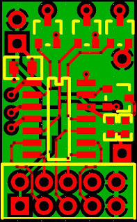

The processor is PIC16F1824 like the last few versions. It includes everything this project needs – SPI for the radio, 4 independent PWMs, EEPROM, ADC, and more than enough code space. The 10-pin header goes to the Nordic nRF24L01 radio module. The only (populated) hardware other than the PIC and decoupling cap are three MOSFETs, one each for CW rotor, CCW rotor, and tail rotor. The stuff on the right were some guesses as to what I might need to operate an ultrasonic transducer. Since I ordered these boards, my testing has shown that ultrasonic distance measurement can’t be done without amplification on the received signal, so I won’t be populating those components.

Because of physical space restrictions, I didn’t end up connecting the radio module with the 10x2 header like this:


Instead I wired it in at 90 degrees so I could put it down inside the frame where the stock board was. I also cut off the trace antenna and added a full-wave wire whip antenna:


My first try at the code to operate the vehicle went like this:
Wait for a packet from the radio
No packet for 4 seconds? Turn off rotors
New packet:
Load throttle value out to main rotors
Load pitch value onto tail rotor
Retrieve trim value from EEPROM based on current throttle value
Skew power to main rotors one way or the other based on trim value
Skew power to main rotors one way or the other based on yaw value
Adjust stored trim value in EEPROM if the packet contains an adjustment

My big innovation was storing 16 different trim values instead of one. I learned from flying these helicopters in their stock configurations that as soon as you got the trim set right,  you’d change the throttle and your trim would be wrong again. To fix that, my code stores an independent trim value for each 1/16th of the throttle range.
The controller is the second version of my tiny transmitter, which was first used with the RC buggy:


The new version of the PCB includes some indicator LEDs, through-holes to mount the battery holder, and gives the microcontroller the ability to switch off power to the high sides of the potentiometers in the joystick. This means it can go to sleep in the off state instead of needing a hardware switch.

Since I want all my RC vehicles to be operated by this one controller, I had the extra challenge of operating a 3-channel helicopter from a single x/y joystick. The throttle and yaw obviously take priority, so those are mapped to stick y and stick x. Pitch isn’t as time-critical, so I have the controller toggle the tail rotor on (25% duty) and off every time the joystick is clicked in. The last command that needs to be sent is trim adjustments. To make trimming a bit more intuitive and to save hardware, I came up with this scheme: while flying the helicopter, I compensate for trim issues by steering right or left with the joystick. Then I press the trim button, and the controller sends a command to the helicopter to adjust trim in the direction that the joystick is currently pushed.
After the first flight, I read out the EEPROM trim values to see how they looked. The trim at all throttle levels was fairly similar, clearly compensating for the added drag of the gyroscopic stabilizer on the top rotor. The first flight also showed me that actively controlling the throttle with this small joystick makes hovering very difficult. The next iteration made joystick movements adjust the throttle level up and down, instead of the throttle level tracking the joystick position. After all these changes, I got the vehicle to the point where I could actually fly it, but yaw trimming just doesn’t work. I can spend a bunch of time getting the yaw trimmed just right, and it will hold a heading for a few seconds, and then just start spinning. Then I finally figured out what the mystery component on the daughter board in the stock electronics is:
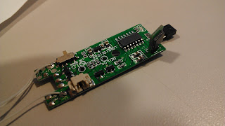


MEMS GYROSCOPE! I couldn’t believe a gyro could be so cheap that it’s included in a $20 helicopter, but it is. I figured out the component’s function by putting its output on the scope and moving the board around. It’s clearly a gyro and not an accelerometer because the signal tracks rotational speed through the entirety of a rotation (including when the rotational acceleration is zero), instead of showing the start and end of the rotation as a rotational accelerometer would.
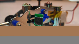

I pulled the gyro off and wired it into my board. I rewrote most of the yaw control code since I’m now taking yaw adjustments from three sources (trim value, controller command, gyroscope) and included adjustable gain coefficients for each term. To my amazement, the first time I flew with the gyro on board, it actually started correcting for yaw drift! But the gain was way too high, leading to oscillations that eventually go unstable. Since the gyro signal’s zero level changes with input (battery) voltage, I maintain a long-term moving average of the signal and then get my current reading my comparing the instantaneous to the long-term.
I then spent way too long tracking down a problem with the radio (turns out you have to read out the RX FIFO buffer even if you don’t want the data, or the radio will start rejecting incoming data and never tell you it has new packets). My debugging work is all done on this proto-board replica of the helicopter electronics:


Working with this setup also showed me the presence of a really dangerous bug: if the radio dies, the MISO line goes high, so all bytes received over SPI are 0xff. This means host software will always think the flag indicating new data is high, and all the new data will 0xff. Because of the way I have my control values encoded (the simplest way), this means that if the radio dies, the helicopter turns all rotors on maximum (and turns right) (and adjusts the trim value left) and never registers that the radio link has died. Yeah, that was one loose wire away from a fourth helicopter flying off into the sunset never to return. Now I recognize the 0xff values and interpret them as a loss of radio link.
Now that I have the gyro working, I need to spend a little time adjusting gains to get flight totally stable. I'll put up a video when it flies better. Only then can I start working on full autonomy. On the side I’ve been working on using ultrasonic transducers to measure distance under my own software control (but yes, it needs active amplification on the receiving end). Won’t it be awesome to just set an altitude with the controller instead of having to constantly adjust throttle to hover!?
Also, this one uses the motor coils to play Ride of the Valkyries when it powers up. As all helicopters should.
Here’s the code that runs the helicopter and controller. It’s mostly unstable from the gyro measurements, but it’s almost there.

Saturday, August 11, 2012

Hyperblaster (modified Nerf Vigilon)


Most afternoons our cubicle area at work turns into a battle zone. Everybody has standard Nerf dart guns but obviously I have to do something that’s different from the rest. I got this disc gun called the “Vigilon,” fired one test shot, and ripped it apart. My inspiration for the final appearance for this is more or less based on weapons from Fallout 3. First step is paint to get rid of the ugly colors.


After masking, I put down a black base coat followed by a dusting of metallic silver. A couple of spots got slight rust effects from a metallic bronze, and then I did the obligatory blood splatter with bright red.


On to electronics. I wired up 4 red-orange XP-Es in parallel and set them into holes in the barrel. I also drilled a small hole and glued in a piezo speaker for sound effects.


The muzzle was the only good place to add lighting on the stock gun, so I got creative and put together this tube thing that’s roughly based on the plasma rifle from Fallout. It’s made from a chunk of a small syringe that some thermal epoxy came in and a length of silicone tubing. A copper wire runs through the tubing to make it rigid. I filled the whole thing with hot melt and set a green XR-E in the end.


At the point where the tube “enters” the body there’s a green through-hole LED. These two greens will be pulsed in sequence to give the appearance of glowing green stuff being injected into the gun.


I hadn’t written code at this point, plus I figured it would be nice to be able to upgrade later, so I put in a programming connector near the trigger.


The clock and data lines from the programming header are shared with the two switches I added. These are formed from music wire and hot melt. They detect when the trigger is pulled and when the slide is pulled back.

I hollowed out the handle to fit a 9V battery, and added a toggle switch for on/off on the left half. The control board is a little breakout board for 14-pin microcontrollers that I used as space filler on a recent PCB order. It’s running a PIC16F1824 and includes two MOSFETs that will run the high-power LEDs. The 5V regulator and current-limiting resistors are freeform wired.


The paint job came out awesome. The tube on the left doesn’t look great, until the power is turned on and it lights up.


I put together this version of the code pretty quickly one night. It handles the green pulsing with an interrupt that calls a state machine to set the two LED levels. The muzzle lights stay on low most of the time and then flash and fade back to low when the trigger is pulled. Pulling back the slide activates a short sound sequence, as does firing. When turned on, there’s a power up sequence that fades all the LEDs on with some sound effects. I wasn’t too happy with the loudness of the sound, but it’s just as well because the sound effects are being synthesized in software by my 8-bit micro so they’re not great anyway. Here’s a clip with all the functions:


Here’s the code.
tag: nerf vigilon mod

Monday, July 23, 2012

Super RGBW Light


I bought this awesome triple-emitter monster light when I was in China at the SEG market in Shenzen. I think it’s a TrustFire TR-500. I couldn’t leave it in its stock “500 lumen” configuration (which is definitely a lie – I measured emitter current at 700mA, which, from the XR-E datasheet, should come out to 3 x 1.70 x 87.4 = 446lm for Q2 parts, and that’s just emitter lumens. Probably around 300 out the front). The first thing was to up the drive current. The stock driver is a boost converter to run 3 series emitters (~9.3V) from 2 18650 cells (~8V). Luckily the main FET still had its markings intact, so I could look it up. It was a surprisingly oversized part with a 50A rating, so I just replaced the current sense resistor with one calculated to hit 1.5A, and it worked. I used 3 T6-binned XM-Ls in cool white, which should give me 551x3 = 1653lm, and probably around 1200 out the front.


I wasn’t happy with the modes that the stock driver had, so I poked around with the scope until I found the pin on the (unmarked) microcontroller that was doing the PWM. They put a big 8-pin micro on there, so I didn’t want to just remove it in case it had some functions other than the modes, so I just cut the PWM pin. From there I just steal 5V from its power pins and run my own PWM into the previously-connected pad on the board.

Plain white light isn’t quite awesome enough, so I needed to add red, green, and blue. I wasn’t willing to give up one of my XM-Ls for a color multi-die emitter, so I milled spots for the extra emitters in the gaps around the edge of the reflector piece, and drilled wire conduits down to the back of the reflector. There wasn’t enough room to put any kind of optic in there. I had to cut out some tiny circular star boards from full-sized ones.

 There was enough room inside the driver cavity to add my own board above the stock driver. I used one of my simple flashlight boards that has an 8-pin micro (PIC12F615), 4 FETs, and 4 current-limiting resistors. For this light I only use three of the FETs and route PWM from one of my micro pins down to the driver board to run the white LEDs.


The color LEDs are a royal blue XT-E and red and green XP-Es. There was a ton of wiring coming out of the back of the reflector but I managed to fit it. I wrapped my added board with electrical tape to prevent shorts. I had all kinds of problems with shorts on the XM-Ls that I fixed with a bunch of carefully cut kapton tape on the underside of the reflector.

The finished product came out great. The code is a modification of my flashlight driver code that I use with color MC-Es, so some of the modes are hilarious with the white so much brighter than the colors. Mode selection is done with a half-press on the switch, and it times out after about 4 seconds and reverts to the first mode. Here are the modes:


High white – the 3 XM-Ls run at 1.5A
Low white – 3 XM-Ls at 10% duty
Low red – the red at 25% duty
RGB stunner – my imitation of the DHS Dazzler. Strobes R, G, B, and combinations at randomized time intervals
Color shift – gradually fades through colors made from combinations of R, G, and B
Color freeze – pauses on a color selected in color shift mode
Firelight – mixes white, red, and green to create light that flickers and imitates fire light
Red –
Green –
Blue –
Police – alternating strobing white and blue
Red beacon – briefly blinks red about twice a second
All on –

Here’s the code. A side note on software: This uses a neat trick I developed for flashlight drivers—instead of the normal means of detecting power loss to cycle modes (with a diode and a big cap), I use RAM retention. When each mode is entered, a RAM location is written with a value that will send the light to the next mode. When power is lost, the micro stops running when its cap drains below 1.8V. RAM is retained until 1.0V, and the power draw is miniscule once the oscillator stops, so this RAM location stays valid for quite a while. When the micro boots up as power is restored, it checks the RAM location for the direction to go to the next mode. If power is left off for a while, the RAM location gets wiped and the micro starts back at mode 0.

Thursday, July 19, 2012

Unnamed Buggy Project: Part 1, RC


I came across this amazing buggy kit made by Tamiya and got one on eBay for about $20 shipped. It has turned into a project without any specific goal beyond doing something cool with the buggy. I think I may do something robotic with it down the line, but the first thing I did was turn it into an RC car. The kit comes with all the mechanics including the drive motor and gearing, but nothing else, so I did the steering actuation and all the electronics from scratch. Here’s the assembled kit (minus the battery holder):


I made some PCBs a while back for random RC projects, so I had this remote control board that takes a standard joystick (the ones used in game controllers) and a Nordic 2.4GHz radio board, all run by a PIC16F1823:

The whole remote assembly worked out really well with a CR123A holder glued on the bottom. I kept the code on this side generic so I can use the remote with different vehicles (I have some helicopter and airplane projects in the queue). The remote just transmits a byte each for the x and y position of the stick, 4 times a second. 

I designed the receiver board for any simple vehicle with one drive motor and one steering servo. It has a PIC16F1823, a connector for the radio board, an H-bridge to run the drive motor, and a servo connector. There’s also a FET that can switch on a load for some other simple function if the vehicle needs one.


The board on the receiving end does all the handling of the joystick inputs specific to the vehicle. In this case it puts the joystick’s y position directly into the variable that runs the H-bridge. This part of the code is ported from the UAV code; it uses timer interrupts to create a PWM signal on two separate pins from a pitch variable, scheduling interrupts instead of using delays so it doesn’t tie up processor cycles. A second timer interrupt generates servo control pulses which are set by the joystick's x position.


That huge electrolytic cap is one of many modifications I had to do to make things work with the big drive motor. It turns out everything goes to hell when you try to run big DC motors on a system with sensitive digital parts. I kept having the whole board lock up when I throttled up the drive motor. The scope showed me I was getting huge spikes on the 3V supply when the brushes in the motor disconnect. To make things work I had to up the capacitance, add a TVS, and put a blocking diode in the connection between the battery and the top side of the H-bridge. Finally things worked:

Back to mechanics. The buggy kit came with this great steering & suspension linkage for the front wheels. It wasn’t so straightforward to add a servo to actuate the steering because of the suspension—the link bar travels up and down as the suspension moves. After sleeping on the issue, I realized that I could make the servo rotate up and down on the same axis that the suspension does.  This also eliminates the need to slot the servo horn because now the servo can ride up and down to account for the change in link length (it’s no longer a slider crank). Shapelock made quick work of this:


The last part is a piece of music wire to link the bar to the servo horn. 


The steering worked out great, plenty of control resolution and a full range of motion on the wheels.


The drive motor didn’t work out so well. After all the modifications to take care of the electrical spikes, the system still just barely worked. I took measurements of the motor and found that it has a ridiculously low coil resistance and relies on the internal resistance of alkaline batteries to operate. I was definitely torturing my little SMD FETs and the lithium polymer battery. Down the line I’ll have to make a specialized motor driver with bigger FETs, current limiting, and a starting capacitor to kick it into motion.

Instead of wait until I find time for all of that, I decided I just wanted to drive it today, so I cut the connection that feeds the top of the H-bridge and ran the drive motor from a separate alkaline battery pack. This certainly isn’t permanent, but I got to have fun driving it around:


I have all kinds of ideas to put into this down the line, so this post is just part 1. Here’s code for the transmitter and the receiver