Wednesday, January 1, 2014
Roku remote mod
We recently got a Roku 3 player, which is awesome. Just a few days into using it, though, I got fed up with having to use two separate remotes for the player and the TV. Before, we could use just one since the cable box remote can be programmed to operate the TV also. The Roku remote can't do this, though, primarily because its connection to the box is RF instead of IR. I decided to modify the controller to send IR commands to the TV so I could use just the one remote while watching stuff on the Roku.
The first step was to decode the protocol used by my LG TV. By watching IR on the scope, I could see that it was modulated at 38kHz, and sends a 4-byte packet for each command. Each packet starts with a fairly long start pulse, followed by 33 pulses 580us long. The 1/0 keying is encoded in the space time between pulses, either 520uS (which I arbitrarily called 0) or 1.6ms (1). This is why there are 33 pulses instead of 32, because the final space has to be framed by a final pulse. I recorded the waveforms for four commands (power, input, volume up, volume down) and noticed that most of the bits are always the same. The only ones that change are the high nybbles of the 3rd and 4th bytes, so when I wrote my transmit function I have it just take in a single byte and split it into those two parts of the transmission. There's also a signal that tells the TV to repeat the last command, which is just a start pulse and a single bit pulse. The remote sends these repeat commands any time a button is held down to avoid repeating the entire packet (saving power).
I wrote my application for the PIC12F617, which is the perfect size for 4 switch inputs and a single IR output. It is also well-suited because it has a PWM output, which I used to generate the 38kHz carrier signal. The PIC waits in sleep until a button is pressed, then sends the command out, and then sends the repeat command if the button is held down, and that's it. I measured the sleep current and it was so low that my meter didn't register anything at all (meaning it is less than 0.05 microamps). Here's my protoboard test setup:
I then opened the Roku remote to see how much room there was inside to add hardware. It is a very well-designed product. Luckily, up front there's a lot of room under the board.
The remote has a feature where you can plug headphones into it and listen to stuff silently, so there are already volume switches. I didn't expect to use this feature much, so I replaced those switches on the PCB with my own and hijacked the external buttons to send volume commands to the TV instead. On the opposide side I added two momentary switches by drilling through the case and epoxying the switches inside. I put the IR LED into a black plastic tube to make the installation neater since it would be recessed into a curved surface, and epoxied it in place.
The PIC sits down at the bottom, and taps power directly from the battery connections on the stock PCB.
In the end it came out very well, although driving the LED directly from the PIC's I/O may have been a mistake because it needs to be very precisely aimed for the TV to receive it. This could also be a carrier frequency issue, though, as the PIC's internal oscillator is not extremely accurate. Here's the code
LED rings
My ring is built into a 3D-printed shell I designed.

It has 7 of the same RGB LEDs and runs a ported modified version of the code for my RGB glasses. There's a small momentary switch to change modes, and it can run any mode the glasses can except those that use motion or sound input. This ring runs from a similar tiny lipo cell, but I wore it on my wrist with a wire out to the ring.
Both of these were exercises in ridiculously small wiring--I had to use 34AWG to connect to the QFN microcontroller. My motivation for these was in part just to test how small I could successfully solder. Here's the code for hers and his
Interactive Jack-O-Lantern
Every Halloween there's a Jack-O-Lantern contest at work, with exclusively LED-lit pumpkins. My entry this year was this interactive pumpkin. It has a “mood” which is portrayed by eyebrow position and illumination color (which fades gradually from green (happy) to red (angry)). The mood changes depending on how close a person is to the pumpkin. From afar he looks happy, but gradually gets scarier as you approach him. In addition to changing color, the light at all times is modulated to simulate the flicker of a candle.
The illumination is provided by an XML-RGBW, driven from LM7135regulators. Distance measurement is accomplished with an ultrasonicrangefinder in the mouth of the pumpkin. The eyebrows are operated by a single small hobby servo, through linkages made from music wire.
Getting those linkages to work out was not trivial as I was trying to drive the eyebrows in opposite directions from the same servo. The linkages are visible in this picture of the inside:
As always, this was a rush job right before the contest deadline, but I just barely got it working in time, and the kids that came to our house later that night appreciated it too.
Here's the code
RGB Glasses update
I recently made a few updates to my RGB glasses. Also, we discovered that they look fantastic on dogs. The big change is to the bracelet: after my new uNRFv2 radio boards came in, I wanted to make a better control bracelet with one. The new bracelet is built on a 3D-printed plastic piece that holds the uNRFv2, the battery, the accelerometer, and 3 momentary switches. (in this photo some of the hardware is not yet installed)
The bracelet performs the same functions as the previous one, but looks better and is less prone to damage because the wiring is protected. It also has a low-power sleep mode instead of a battery disconnect to shut it down. I also wrote an update for the glasses which makes a few mode changes, and adds a momentary switch on the glasses that allows mode changes, which means the glasses can be used without the bracelet. The switch also allows the radio channel to be changed in case of interference. The bracelet software has a provision to change the channel to match. The most notable mode update to the glasses software is lightning mode:
Here's the code for the bracelet and the glasses
OLED Interface Board
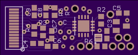
While preparing for my Veloster proximity sensor project, I found these great OLED displays on eBay. They are monochrome 128x32, self-illuminated (OLED), graphical displays with a convenient serial I2C-ish interface and only cost about $4. The only downside is they have a 14-pin flex connector and require some external passives, so connecting to them is a challenge. The first one I used, I hand-soldered 30AWG wire to the flex connector, which was not easy (wiring visible on the right in this picture).
The entire board is about the same size as the display, so the flex connector can fold over and sandwich the two together into a very small package. After getting the boards working, I wrote a piece of code that implements and variety of methods of displaying data, including bar graphs, moving time plots, and multiple digit sizes. The framework code also has a 5x8 pixel font included. At this point, the only real use I've put these to was to test out a new display layout for my Veloster proximity sensors before installing the update in the car. Here's the framework and the display test as an example. This board is available open-source on OSHPark under my profile here
Saturday, September 28, 2013
u_nRFv2 board
I just finished designing this new board this week, version 2 of my micro-nRF board:
As I'm writing this now, I realize that I never wrote a post about the first micro nRF board. You may have seen pictures of them in previous posts like my first LED glasses. The original board was intended to be a general-purpose wireless board, using a PIC16F1824 and nRF24L01+. I designed in the SOIC version of the PIC because I have lots of them lying around because they're used in a product at work, but I later regretted this decision because of the size. I also frequently ran into issues with the lack of I/O available--the PIC has 12 I/O, the radio uses 6 and an LED uses a 7th, so there's not much left for the application.
I designed version 2 to be smaller and to include more I/O. This version uses the PIC16F1829 in the QFN package. I got rid of the trace antenna because I usually use wire whips, and it's not worth paying for PCB space that only has a wire. The overall board is smaller than the nRF24L01 radio modules I buy from eBay (this is still the cheapest way to get all the radio components--I just transplant the chip and all the passives onto my board [except the crystal, I had to reduce to a smaller package for v2]). The 1829 has 18 I/O which leaves me 11 available for the application. I still included the LED indicator, and I connected one pin to an N-channel MOSFET on the board.
This board is my first order from oshpark, which looks like it will be awesome. My boards went to fab yesterday, we'll see how they turn out. Here's the schematic:
I wrote a software template to use these boards that gets the radio running in either transmit or receive mode, here it is.
I designed version 2 to be smaller and to include more I/O. This version uses the PIC16F1829 in the QFN package. I got rid of the trace antenna because I usually use wire whips, and it's not worth paying for PCB space that only has a wire. The overall board is smaller than the nRF24L01 radio modules I buy from eBay (this is still the cheapest way to get all the radio components--I just transplant the chip and all the passives onto my board [except the crystal, I had to reduce to a smaller package for v2]). The 1829 has 18 I/O which leaves me 11 available for the application. I still included the LED indicator, and I connected one pin to an N-channel MOSFET on the board.
This board is my first order from oshpark, which looks like it will be awesome. My boards went to fab yesterday, we'll see how they turn out. Here's the schematic:
I wrote a software template to use these boards that gets the radio running in either transmit or receive mode, here it is.
Wednesday, September 11, 2013
RGB Glasses
After my green LED glasses worked out so well, I decided to expand on the idea and build a new pair with more capabilities. The most notable upgrade is they are RGB instead of just green, but they also include 7 individually-controlled groups instead of all LEDs operating the same. This allows me to run animations spatially across the frame by showing different colors and brightnesses at different locations.
The LEDs I used are Cree PLCC6display LEDs. These are perfect for this application because they have the red, green, and blue emitters set behind a diffused optic that mixes the colors, and the package is shaped to throw light only forward without secondary optics. I had a rough guess at how many LEDs would fit on the frame based on how many XP-Cs I fit onto thelast pair (about 53). Wiring that many LEDs with three times the connections for colors would be impossible to do by hand so I started laying out a PCB.
I used ExpressPCB for the project so I could get the boards quickly. The layout software is not very full-featured, so my first step of modeling the shape of the glasses frame was tedious. I'm using the same glasses I did before, they're cheapo sunglasses from Walmart. Once I had the frame modeled I started filling it with LEDs. The recommended footprint for these LEDs is oblong (despite the LEDs being square) to give runout room on the solder pads, so I had to pay attention to keeping spacing consistent between the horizontal and vertical segments.
I had originally planned to include control electronics directly on the back of the PCB that held the LEDs, but after chaining together the R, G, B, and common anode channels, there was no room left at all. This meant I wouldn't be able to have as many individual groups as I wanted. The final LED count came out to 70, which severely limited the possible arrangements of groups I could choose from. At this point I decided that the best plan for current regulation would be to use AMC7135 regulators for the low side of each color channel. These regulate to 350mA, and since the LEDs are rated for 35mA max per color, I split the LEDs into 7 groups of 10 LEDs each. The cathodes for all 70 of each color are connected, and the common anode for 10 LEDs in each group are connected, leaving 11 connections to wire out to the control board. 7 groups is annoying to work with in an 8-bit system, but it worked out well based on the shape of the glasses—two segments on top, two on bottom, two sides, and the nose in the center.
The control board uses a PIC16F1829. Six pins are devoted to communication with the nRF24L01+ 2.4GHz radio module through the SPI port. Seven pins operate the P-channel FETs that switch the high side of each LED group, and three pins on PWM channels run the low-side regulators for each color. That left only one I/O pin open, and since I knew I wanted to do a sound-reactive mode at some point, I broke that pin out to a wire pad in case I decided to use it. I designed the board to allow the radio module to plug in and stack on top of the control board, but in the final assembly I decided that was too tall and wired it out to lay next to the control board.
In order to get the price break on ExpressPCB's Miniboard Pro service, I split the LED sections up and packed them into the 2.5x3.5” space to be cut out by hand. The board also includes the glasses control board and the remote control board (worn on the wrist). After assembling the glasses I realized that splitting them up like this was much better than trying to keep them as one piece because they needed to wrap around slightly to conform to the shape of the glasses, and the split sections allowed bends. I actually ended up putting extra cuts in the PCB later to bend it further.
Cutting and populating the boards was straightforward once I got them. Boards are connected to the glasses frame with hot glue, and everything is wired together with black 30AWG wire-wrap wire. Since these are fairly low power, I included a small 120mAh lithium ion cell directly on the glasses so they can operated standalone (with no external battery pack and cable). In most modes, this cell can run the glasses for about an hour.
After the initial build I did add a sound-reactive mode and the hardware required to do that. I used an electret microphone with an opamp. The opamp has its input ac-coupled to the microphone, puts it through a 100:1 gain, ac-couples the output with a Vcc/2 bias, then low-pass filters that to shed anything higher than 250Hz. This is fed directly into the ADC on the microcontroller. The opamp circuit was free-form assembled and wrapped in heatshrink, which occasionally seems to cause a weird feedback loop effect.
Even with this level of complexity in the hardware, the software was more complex still. I set up a multiplex routine in the timer interrupt that cycles through each of the 7 groups at 1kHz. There are two arrays that control the output—brightness and color, with 7 bytes in each array corresponding to each LED group. Brightness is a full 8-bit value that sets the overall intensity of the light on all three channels in the group. Color is a 5-bit value (+1 for white, so 33 values) that corresponds to a mix of red, green, and blue to make any color. This way I don't have to crunch a lot of data to set individual R,G,B values for each channel, I just select and manipulate a single color value. Every time the multiplexer is called, it uses the color value to call out to lookup tables for the R, G, and B values that correspond to that color. These values are then multiplied by the overall brightness value for that group, and finally bit-shifted back into the 8-bit range before being output onto the PWM for the color channels.
With the multiplexer running in the background, the main loop can run color and brightness patterns by manipulating the two 7-byte arrays. Animations are often made simpler by moving values around within the array instead of calculating them from scratch. The software is built in my usual structure, with the main loop only acting as a task handler and single instances of tasks initiated by interrupt actions and sometimes by other tasks.
The modes of operation are split into brightness modes and color modes, and a combination of any brightness mode with any color mode is allowed. At the time of writing this, there are 21 color modes and 17 brightness modes, for a total of 357 possible operating modes. (while we're crunching numbers, I like to quote the total possible operating states at any instant (loosely defining “instant” because I’m talking about time-based PWM for brightnesses plus multiplexing) based on the degrees of freedom I have. With the original green glasses, it was 2^8 = 256 states. These glasses have: ((2^8)^3)^7 = 3.74x10^50 possible states.)
Demo of color modes (read the list first, otherwise it's hard to tell what's going on):
Demo of brightness modes:
Color modes:
Smooth chase – rotates the whole spectrum of colors around the glasses, gradually transitioning between colors
Gradual chase – hard to describe; chases around the glasses with a new color that very gradually transitions through the spectrum. Watch the video to see
Full chase – rotates the whole spectrum of colors around the glasses; mostly obsolete after I wrote in smooth chase
All same – gradually fades through the whole spectrum, but with all 7 segments acting together
Stepping – steps through all the colors one by one, all segments together
Chase stepping – like stepping, but when it transitions to the next color, the new color chases around the glasses until it has filled all 7 segments
Fire – emulates fire with reds, oranges, and yellows. Pseudo-randomly generates a new red-orange color on the bottom row, then advances that color up towards the top of the glasses, turning it yellower as it goes
XYZ – not yet working. Attempting to set R, G, B color levels from accelerometer X, Y, Z values
White -
Red -
Green -
Blue -
Violet -
Yellow -
Turquoise -
Pale blue -
Pale green -
Eyes blue green – one eye blue, the other green, middle segment is the color in between
Eyes blue red -
Eyes red green -
Stoplight – red on top segments, yellow in the middle, green on bottom segments. I added this to be used with the VU meter brightness mode
Brightness modes:
Sound-reactive – pulses brightness to the beat of music
VU meter – shows audio levels like a meter, rising higher on the frame with louder sounds. Not yet working very well
Chase – chases around the frame
NRZ (non-return to zero) chase – chases around the frame but doesn't turn segments all the way down to off
DC (discontinuous) chase – chases from one corner of the frame all the way around and then goes away, repeats after short delay
Bracelet pulse – reacts to motion, same function the old green glasses did
Auto pulse – pulses overall brightness up and down
Eyes pulse – fades brightness back and forth between the two eyes
Bracelet strobe – same as bracelet pulse but strobing at the same time
Strobe -
Bracelet chase – chases brightness around the frame, but scales overall brightness in response to motion
Low chase – chase at lower overall brightness
Twinkle – randomized flickering of all segments (originally added for use with the fire color mode)
Slight twinkle – less intense effect
Max – full brightness
Low – 6.2% brightness, the lowest it can go and maintain full resolution on colors
Very low – 2.7% brightness, colors lose half their resolution at this level
There is a color mode updater that handles changing color actions when it is called periodically (triggered by timer interrupt), and a similar brightness updater. All of the changing modes are created by state machines that are called periodically, make quick updates, and go back to the main loop. Other task handlers are the radio update to get new data, mode changers, and the audio analyzer.
All of these functions are controlled by the bracelet. The bracelet has the other PCB that was on the board, which is basically just a PIC16F1824 with a radio module connector and breakouts. It sends data up to the glasses over the 2.4GHz link based on input from two buttons and the 3-axis accelerometer. This is all powered by a tiny 70mAh lithium ion cell. All of these components are attached to a nylon watch band with hot glue. One of the switches on the bracelet advances color mode, and the other advances brightness mode.
In the end, I couldn't be happier with how these came out. I have to fight the urge to wear them everywhere all the time. Thanks for reading this extremely long post; you can see more pictures of these if you scan the crowd in pictures from Raleigh-area EDM shows in the coming months:
Here's the code for the glassesand the controller.
Subscribe to:
Posts (Atom)