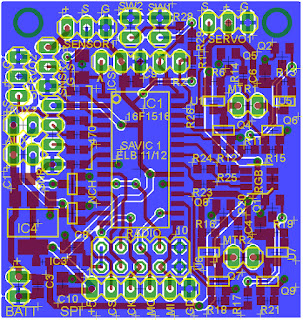
I finally got my Semi-Autonomous Vehicle Integrated Controller (SAVIC) boards in from batchpcb. I used this project to learn to use Eagle to do layouts; it’s my first Eagle board and my first batchpcb order. I set out to design the SAVIC board so that I could quickly and easily get moving with small robots instead of custom building new stuff every time I wanted to try something new. This board is meant to include all the features you’d need to get started on a small robot or RC vehicle, and intended to be modular so it can be expanded upon. SAVIC has:
• 2 H-bridges for DC motor control
• 2 high-current sinks for single-polarity loads with PWM
• 2 servo outputs
• 2 analog sensor inputs
• 2 digital (switch) inputs
• RGB status LED
• nRF24L01 2.4GHz radio
• HC-SR04 ultrasonic rangefinder connection
• SPI expansion connection
• PIC16F1516
I managed to pack everything into a 1.5x1.6 inch board. I had learned something about H-bridges from the board I originally used on the RC buggy. The P-channel FETs in that design had their gates switched by the drains of the N-channel FETs, so they were directly connected to the load. That worked for very small motors (in my 6” helicopter), but when I put a bigger DC motor on it, the inductive spikes ruined it. For the SAVIC board, I used bipolar transistors to invert the gate drive signals for the P-channel FETs.
The only issue I had with the first one I assembled was voltage limitations on the peripheral devices connected to it. I designed it to interface to HC-SR04 ultrasonic rangefinders because they’re so cheap and easy to find, but they have crippling supply voltage requirements. They don’t really work outside of 4.5-5.5V, where the PIC can run from 1.8-5.5V. The Nordic radios can’t go higher than 3.6V (but luckily the signal levels can be higher), and servos need 4-6V. On the board I put a 5V regulator to run all digital devices except the radio, which has its own 2.5V regulator. Servos pull tons of current when they move so I didn’t want to load the 5V regulator with them, so they’re powered directly from input voltage (as are the H-bridges). The problem is if I power the board with 6V, the 5V regulator doesn’t have enough overhead so the digital supply isn’t high enough to operate the rangefinder. If I go higher than 6V input, the servos get overvolted.
The next revision will have to fix this somehow (probably by ditching the HC-SR04), but for now I’m running the board from 2 Li-Ion cells (8.4V) and putting a small adapter for the servo with an independent voltage regulator on it. One big advantage of this setup is that it overvolts the drive motor on the buggy like crazy, which gives it awesome speed and power.
I’m trying to transition to only working in C for robots, so I rewrote most of the functions I had already written for other RC vehicles. It’s programmed to used the same radio packets as the helicopter so I can use the same controller for both. The code has drivers for both servo outputs, bidirectional pwm for one motor, talking to the radio, and rangefinding. Once I got it operating well under remote control, I added an autonomous mode that just wanders around and avoids crashing based on data from the rangefinder. Autonomous mode is activated by a button on the controller, so I can switch between RC and auto on the fly.
Here’s code for the SAVIC board. Controller code will be in the next post.


No comments:
Post a Comment