I recently built this portable soldering iron that uses Hakko T12 tips and is powered from a QC2-compatible power bank via USB. It is similar in size and form factor to the TS100, which I like, but I wanted to build this to make a couple of improvements over the TS100 that would be more useful for me:
- use cheaper and more widely-available T12 tips
- direct power from USB port
- able to negotiate with QuickCharge power sources for 12V
- impoved tip-to-handle distance
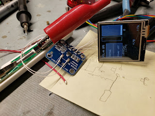
I was able to make the hardware fairly simple by using a trick to measure the thermocouple voltage from the tip. I initially planned on using an IC intended to be a thermocouple amplifier such as the MAX6675, but found them to be too slow to make the conversion. Since the heater in the T12 tips is in series with the thermocouple, the heat must be turned off while the measurement happens, meaning the measurement needs to be very quick to allow for high duty cycles on the heater. I realized that there was another chip I've used extensively that can accurately measure small voltages - the INA219, which is intended to measure voltage across a shunt resistor.
After a quick test to see if I could get reasonable signals from the T12 tip this way, I took some measurements and came up with a transfer function to get tip temperature from the shunt voltage reported by the INA219.
With that settled the schematic ended up looking like this:
Using the INA219 to measure thermocouple voltage also gives a nice feature for free (without extra hardware) - it can also measure the input voltage to see if the negotiation for 12V has worked.
I got the tip holder PCB from a cheap T12 handle from Banggood and trimmed it down significantly to save space. On the back of that I attached a micro USB jack on a small breakout board. Underneath that is a USB type C jack as well, so that the iron can be powered using either type of cable.
In order to do the QuickCharge 12V negotiation, the data+/data- lines from the two jacks are tied together and then connected to resistor dividers that are controlled by I/O pins so that the microcontroller can selectively apply 0 and 0.6V to the lines. I learned about the QC protocol from this page.
The whole housing was 3D-printed in ABS. To make sure the handle can't get too hot and soften the plastic, I included a thermistor to measure internal temperature near the front of the handle. The firmware will force a cool down period if this gets too high.
The iron also includes a tilt switch pulled from the same T12 handle that I got the PCB from. This lets the firmware know when the iron has been put down so that it can automatically go to standby and resume once picked up again.
The display is a 96x16 pixel SSD1306 OLED display connected to one of my custom boards that is a breakout for the PIC18F26K40 with solder pads and support hardware for small OLED displays.
The display and board are mounted in the top of the handle and then I tucked the INA219 into a free corner and wired it up with 34AWG magnet wire.
Two momentary switches are used to control the temperature. The UI is fairly basic but tries to implement some good automatic features - retrying the 12V negotiation until it gets >10V, automatic standby and resume, automatic cooldown if the handle gets too hot, automatic tip detection, etc. At all times the display shows input voltage, internal temperature, tip temperature, tip setpoint, and the state of the switches and tilt sensor. The remaining space is a scrolling text of the current state including how much time until automatic standby, etc.


