I hacked my DJI mini 2 to build a payload dropper that I can control from the Fly App. Here's the video:
Wednesday, April 14, 2021
Friday, February 5, 2021
Simulating Hoot Owl Hoot! in Python to find the best strategy
Here's a board game simulation I wrote in Python to work out which strategy is the best to win the kid's game Hoot Owl Hoot!
My 5-year-old loves to play this board game made by Peaceable Kingdom where the players work cooperatively to move the owls along a path to the nest before running out of time.

We were all playing one day and ended up debating on what the best strategy is to win - do you always move the piece that can go the farthest, or do you always move the piece in the back? It didn't seem like a clear answer at first - there are several game pieces and one moves on each turn to a color space chosen from the shuffled deck of cards, but they can jump over other pieces if there is one occupying the space they would otherwise land on. I thought it was best to move the one in the back so as to not strand one far behind the others (and therefore maximize the chance of getting to jump over spaces), while my wife thought you should always figure out which piece can go the farthest and move that one.

Not satisfied with just not knowing the answer, I wrote a Python script that simulates the game. In this script only four owls are used (the way we usually play) and it doesn't bother including the sun chip - for my purposes it was sufficient to just see which strategy won in the fewest moves.
The game is fairly simple to simulate - I made an array that holds the actual colors on the path which I copied from the game board, and there is an array of owl positions on that path.

Each turn, a random color value is chosen and then some simple logic can move an owl forward to the next matching color while also checking for owls occupying the space that it could jump over and checking if it has reached the nest:

I wrote functions that would be used to evaluate the potential moves for each strategy by simply finding the rearmost owl:
and finding the longest potential move:


This got wrapped up in the main program that is run in a terminal and lets you choose the number of iterations to run and then gives the statistics on the result:

It turns out that the two strategies are remarkably close, despite leading to very different games each time, but if you run it through very many iterations, the longest move strategy tends to be best most of the time:

Here's the code. It's a bit messy with some nearly-duplicate functions since I built it up layer-by-layer and included a lot of stuff earlier on to print out the whole game board and detail each move to make sure the algorithms were correct before just running them without printouts to collect the statistics.
Thursday, January 14, 2021
Friday, January 8, 2021
Hacking and upgrading a 3Doodler 3D pen


I recently received a 3Doodler 3D pen after only using cheapo $20 no-name 3D pens for several years (like this one). While the mechanical design on this one is nice, it had a few issues that left me not wanting to use it in its stock form:
- used 3mm filament instead of the 1.75mm that my printers use
- used switch presses as stop and start commands instead of momentary (hold to extrude, release to stop)
- slow extrude was not slow enough (not their fault, I always want a slower extrude to better do detail work)
- annoying behavior of the cooling fan (just runs along with the extrude regardless of temperature)
- closed-loop feedback control on the extrude speed to achieve slower speeds and better consistency
- add temperature monitoring of the cold end of the extruder to more effectively use the cooling fan
- change the power input to USB-C

After the filament size conversion I worked on the speed control upgrade. Initially I tried to add rotation speed measurement to the bevel gear on the output of the motor gearbox, by drilling a hole and adding a 2mm magnet, and mounting a hall effect sensor above it on the PCB:


I could then check the placement with a hall effect sensor and see how close I had to be to detect it. The camera frame rate happened to sync up with the motor speed here:
I mounted the hall effect sensor to the brass plates of the gearbox with CA glue, and it fit entirely within the envelope of the gearbox, so I didn't have to make any changes to the plastic frame that the motor fits into:
This new setup gave rotation measurement periods in the range of 50-200ms which was much more usable to close the feedback loop on extruder speed.
The cooling fan upgrade was much simpler, I just installed a thermistor on the cold end of the extruder to monitor its temperature. This is an 0603 thermistor wrapped with kapton and mounted to the cold end with CA glue:


Along with the microcontroller, the board has a FET and gate drive transistor for the heater, a FET and flyback diode for the fan, a motor driver (the SOIC-8 package), an RGB LED, and all associated passives. I took measurements on the microcontroller pins while operating the pen and came up with this list of pin functions:
1: VCC 5.05V2: pulled low if switch is back (off)3: pulled low if switch is forward (ABS mode)4: icsp, not used in circuit5: heater pwm 1khz active high6: 2.5V reference for adc7: rear switch8: fan pwm 200Hz 20% duty9: extruder active low (high = backward)10: red led active low11: green led active low12: blue led active low13: extruder forwards active high 600Hz 50% fast 20% slow14: front switch15: hot end temperature. lower=hotter. pla = 1.51V, abs = 1.24V16: ground
With all those identified I could safely remove the stock microcontroller and install a new one. I chose to use the PIC16F1579 in a QFN package, and mounted it upside-down in the middle of the old uC pads with CA glue:

I wired up the new microcontroller, using 34AWG enameled magnet wire. I also added a small chunk of PCB to hold the pull-down resistor and capacitor used to read the added thermistor, as well as a piece of a PCB to act as a programming port:

With that the hardware changes were complete and I moved on to firmware. For the initial work I set up a temporary UART debugging output so I could watch values for hotend temperature and extruder speed in order to tune those control loops. I ended up getting decent results for both using PD control loops, although the way I implemented it also has a sort of half-assed integral term since the P and D term results get added to the current duty cycle instead of calculating a new duty cycle every loop. After all the hardware and the two control loops (extruder speed and hotend temperature) were working, I figured out the new UI I wanted. Here it is as I wrote it before coding the state machine that runs the UI:
/*switch on: rise to temperatureonce up at temp, allow extruder movementfront switch is momentary forward extrudeshort retract after forward movementclick rear switch shifts between 3 speedshold rear switch backs out filament until releasedsafety timeout 3 minutesbroken thermistor detection*/
The final source code is uploaded here: https://github.com/tterev3/3D_pen
In the course of finalizing the firmware I ended up wanting to fully reassemble the pen but still be able to reprogram, so I added a new programming port (this time just a flat PCB onto which I press a pogo pin programming header). The pen had this useful port on the side with a removable cover, which wasn't used for anything in the stock product, so I added the port there and could fully reassemble it:

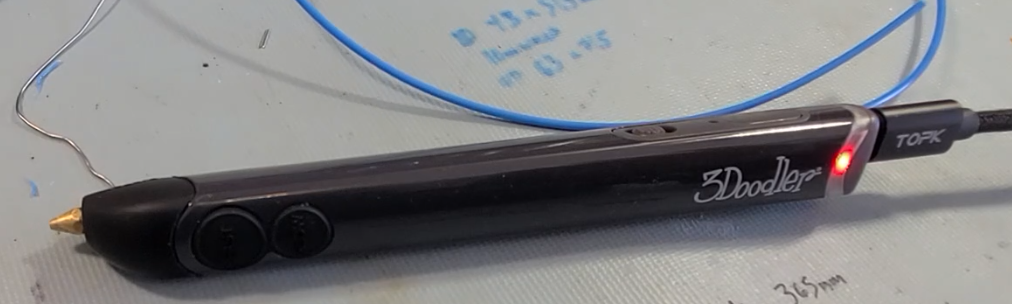
Around this time I also decided to add one last hardware upgrade and swap out the barrel jack for a USB-C jack, which required a bit of trimming of the rear cover:


After all these changes I'm quite happy with this pen now - it's much nicer hardware to use than the cheapo pens, can do lower extrude speed, and can be run from a power bank since it's now 5V USB-C powered.
Thursday, November 19, 2020
Saving a broken tablet with a charger hack

I found this Samsung Galaxy Tab S in an e-waste bin. It didn't have any visible damage, but it had been thrown away because it was dead and wouldn't charge or react at all when plugged in. My USB power meter showed it would only pull about 10mA from the USB cable.

Since this was one of the older designs with the removable back cover, I could easily open it up and directly access the battery connector. By charging the battery from a bench supply, I got it to wake up, and everything seemed to work normally except for charging. The previous owner had installed some kind of aftermarket OS on it that caused it to get stuck in a boot loop as soon as I tried to do a factory reset, so I had to spend a while figuring out how to use Odin to restore the stock OS. After that diversion it was wiped and working normally, but still unable to charge.
I couldn't find any visible signs of damage, and I could confirm that the connections to the USB port were still good - in fact the system could still detect 5V when plugged in and indicate that it was charging, but no current was actually going into the battery. It also was still able to accurately report battery charge because it was based on voltage. This meant that if I could add something to charge the cell, the whole thing could be restored without having to dig further into the real source of the failure.

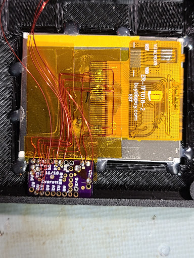
I prepared a small board to hold a TP4056 charger IC. This was cut from blank flex PCB material since everything needed to stay very low profile to fit in the case. A higher-current charger would have been preferable since this is a 4.8Ah cell, but the only options I had would have required a PCB with a lot more support components and would have ended up being too thick. The TP4056 is set up to charge at 1.2A, which is a slow charge but probably good enough for the use case for a tablet. One other disadvantage is that it will only charge to 4.2V while this is a 4.35V cell, so it only gets to 92% (as estimated by Android). I figured these disadvantages were acceptable tradeoffs for keeping the repair simple and getting it working quickly.

I probed out the connections for 5V and ground on the USB connector daughter board, and tapped into these with 34AWG magnet wire.

From there it was very simple to wire in the new charger. I was lucky that system ground was connected to battery negative, so this charger architecture would work. All I had to do was wire 5V and ground to the TP4056, and then connect the output from the charger to a battery+ connection next to the battery connector.
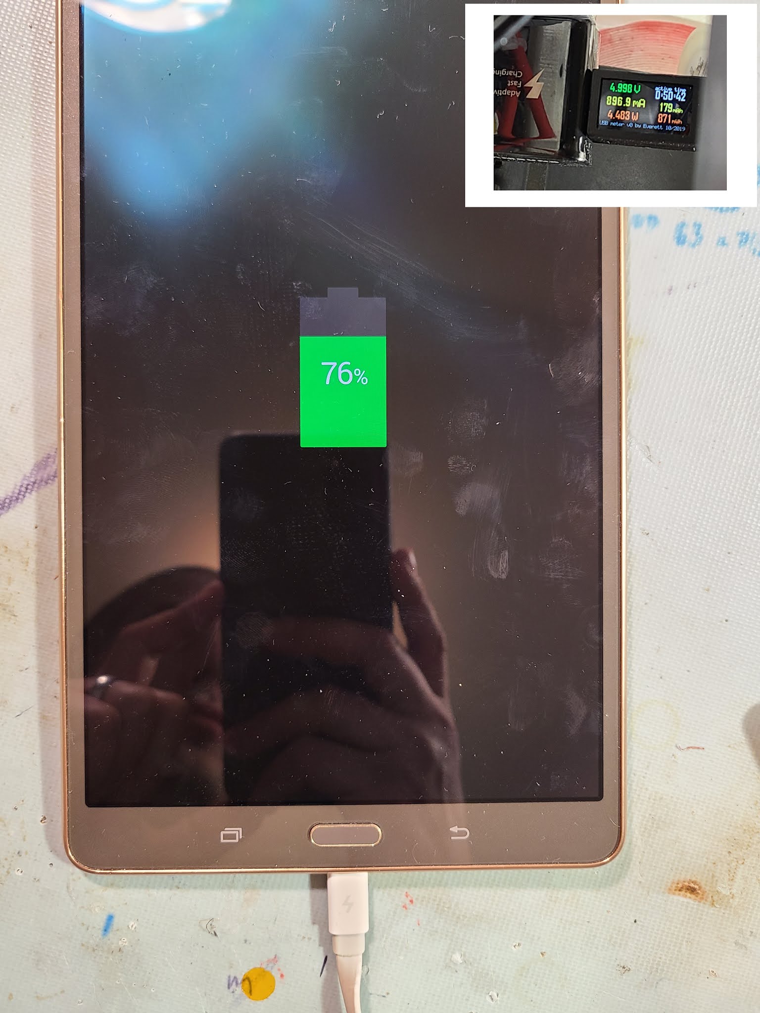
I then plugged it in, checked that everything was working on the USB meter, and closed up the case. The tablet now works normally and has no visible external changes - it just charges a bit slower and tops out at 92%.
Thursday, October 29, 2020
Building an instrumented IP5328P power bank

I bought some nice 21700 cells and an IP5328P power bank board with the intent to build a large (24Ah) power bank. I've done lots of power bank projects in the past where I added voltage and current instrumentation and displays to be able to monitor what was happening while using the power bank, and for this new one I wanted to use a nice RGB graphical display (whereas older projects used black and white OLED displays).
When I received the boards I started doing some reverse engineering with the goal of taking my standard approach of adding in current sense resistors, voltage dividers, and INA219 power monitors to get the data I needed. After taking a look at the IC's datasheet though, I realized that all the information I wanted was available over an I2C connection, so I'd hardly have to implement any hardware at all. The I2C bus is available by connecting to some lines that are otherwise used for the indicator LEDs:

The datasheet had no information on the available registers though, but luckily an EEVBlog forum user had come across the needed documentation and share it in this thread. With that and a whole bunch of Google Translate I got my microcontroller (PIC18F26K40) talking to it.
I wired up my microcontroller breakout board to the 1.8" RGB display, which I manually wired up to with 34AWG magnet wire (trying to keep things as low-profile as possible).

And after connecting I2C as well as the INT signal and power to the main board, I was able to pull data and display it on the screen. You can also see that I relocated the inductor to save on height.

I did a bit more work on the 3d-printed housing, including some manual adjustments with dremel and 3D pen, and got the display and power bank board installed. At this stage of assembly I spent a long time writing all the graphics code to show status and data. After getting that to a point I was happy with, I welded up the cells and installed them:

And closed it up:

Here's a demo showing the display in action:
Friday, September 25, 2020
Min/Max light version 2

Here’s version 2 of my Min/Max light – a flashlight built from scratch with the aim of having the minimum size with the maximum functions. I shared version 1 here.
This time around I designed and built this light from the ground up instead of modifying an existing light. I included every feature I could think of for a small EDC light:
- adjustable brightness
- red, green, and blue color modes
- ultraviolet
- a green laser
- USB-C rechargeable
- temperature control
- battery power instrumentation
- a graphical color display
- a tail switch as well as up and down switches
- a touch sensitive panel
- a tailcap magnet
and of course this includes all the functions of my previous MELD flashlights – strobes, configuration options, automatic shutdown, etc.
I managed to fit it into a final size of 51×30×17mm.

The structural parts are 3d printed in ABS. a central plastic frame holds all the electronics wrapped around the lithium battery, and there is a heatsink formed from a folded copper sheet that wraps around the right side.

To get this to fit into the smallest package possible, I put all the electronics including the emitters onto a single flexible PCB. This PCB is folded to cover 4 sides so that it can hold emitters on the front, a display on the side, switches, touch panel, laser, and charge jack on top, and a tail switch on the back.

This light does all the same stuff as my other MELD lights, with the addition of the green laser, USB charging, a third switch, and of course the color display. The the display always shows mode, LED temperature, battery charge status, drive current, and a remaining runtime estimate.
Here’s a video with details on the build process and demos of the finished light:
Subscribe to:
Posts (Atom)