
Here’s another example of a totally useless project that
I took on with no justification other than “because I can.” I love lights. At
EDM shows, everybody loves lights. After going to my first Bassnectar show I
decided I had to make some kind of wearable lighting system to wear to future
shows. Not wanting to spend infinity hours stitching LEDs into clothing, I
settled on LED glasses. Just lighting up isn’t enough though—they had to be
painfully bright and do some cool effect that can complement music.
On a long
drive last year I thought of an idea for this—just pulsing lights to the music
has been done before, but what about making the lights respond to body motion
as you move to the music? The idea solidified as an accelerometer to measure
hand movement which would control the brightness of the LEDs. The accelerometer
had to be mounted on my wrist and get signals to the glasses on my head, so I’d
have to run wires along my arm. No way, using wires on a wearable system sucks,
and I have a stack of uNRF boards waiting for good applications, so I went with
2.4GHz.

Software: I already had basic code running on my uNRF
boards to send and receive, so the radio link was taken care of. I went through
a very interesting design process with regards to the signal flow from
accelerometer to LEDs. In my initial exploration of the idea, I programmed one
microcontroller to handle the entire process from reading acceleration data to
outputting the LED PWM signal. I wanted the system to work regardless of
orientation of the accelerometer so I set up the software to sample all three
axes.
The system only needed to respond to fast movement, so I wrote an
algorithm that calculates a long-term (10-second) moving average for each axis
and then calculates the absolute value of the difference between the
instantaneous reading and the long-term average. These values for all three
axes are summed to create a single value that represents total movement in the
short term. This value is then fed into two processes that generate the PWM
output.
In order to create an effect that looked good, I wrote two independent
processes that increase and decrease the PWM duty cycle. The increaser
increments PWM any time the scaled movement value is greater than the current PWM
value, and the decreaser decays the current PWM value at a steady rate. These
two processes are triggered by timers that run in the interrupt service routine
so they can each be configured to operate at different speeds. The values I
settled on run the increase at 1000Hz and the decrease at 250Hz.
All those
processes working together created the whole signal flow, but I had to cut it
into two sections separated by the radio link. To do this, I picked the point
in the flow with the lowest bandwidth, which ended up being the total
short-term movement value. This value is calculated in real time by the
microcontroller on the wrist unit and then transmitted at 50Hz to the board on
the glasses. The micro on the glasses takes the movement value and handles the PWM
increase/decrease and outputs it to the buck driver.
The final software pieces
were some modes which I could switch by pressing a momentary switch on the
glasses—I included motion control, lightning mode, strobe mode, and constant
brightness. Lightning mode is a really fun one where the LEDs sit at low power
and then pulse at full current for 50ms any time the accelerometer reads over a
certain threshold; this gives a really cool effect of being able to throw
lightning strikes. I also included the ability to scale down the brightness in
all modes to 50%, 25%, or 12% (in case people at clubs yell at me).
Here’s a
preliminary software test before any hardware was built:
Build: I found some really cheap cool-looking sunglasses
and started building the LED array. This involved a totally insane process of
soldering 60 XB-D LEDs directly onto two strands of 30AWG bare wire, which I do
not recommend. Nor do I recommend throwing that away and repeating the process
with XQ-B LEDs when LED issues appear, and I
certainly don’t recommend trashing that and building a third array with color XP-C LEDs. But yes that
is what I did.

When I had to build the array for the third time I decided to
switch to a color instead of white and settled on green, so the final product
used 56 green XP-C emitters. I build the array in two sections and laid them
onto the glasses frame with hot glue. The technique I used was to lay dabs of
hot glue on the plastic frame, lay down the leds (shaping by bending the wire
between emitters), and then heat the LED strip with the soldering iron to melt
the glue.

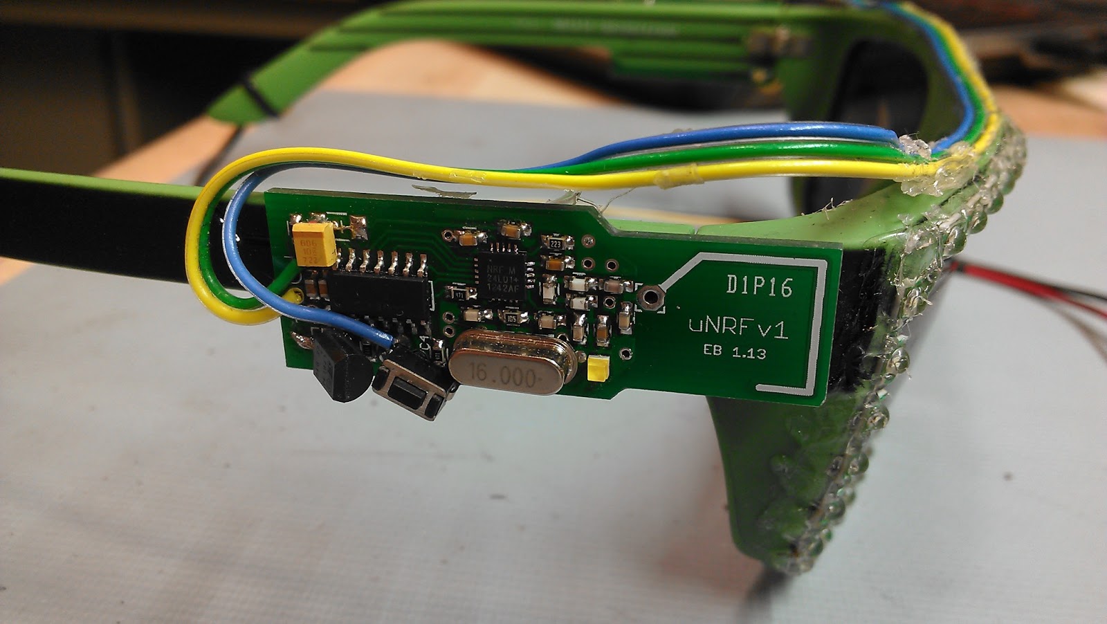
With LEDs down, the rest of the glasses build was just
mounting the uNRF board on one side and the MAX16820 board on the other. I put
together a simple 2S1P battery pack out of IMR 18650 cells with a long cable
and a connector to power the system. Assuming an average of 50% brightness
(certainly an overestimate), the pack should give me 2.9 hours of runtime.


The wrist unit was made from a uNRF board, the accelerometer board, and a small lithium polymer battery (which should last approximately forever at an average current draw of 1.3mA). To make it actually stay on my wrist and be removable, I made a bracelet out of shapelock to which all the components mount.

The wrist unit was made from a uNRF board, the accelerometer board, and a small lithium polymer battery (which should last approximately forever at an average current draw of 1.3mA). To make it actually stay on my wrist and be removable, I made a bracelet out of shapelock to which all the components mount.

